TW-72 Instructions for XL-160 and XL-180 Do not attempt to use or maintain this unit until you read and understand these instructions. Do not permit untrained persons to use or maintain this unit. If you do not fully understand these instructions, contact your supplier for further information.
Contents Container Safety ....................................................................... 1 General Information .................................................................. 2 Specifications ............................................................................ 2 Operation ................................................................................... 4 Component Descriptions ............................................. 4 Withdraw Liquid from the Container ..........................
Pressure Hazard – The containers covered by this literature contain liquefied gas under pressure. Sudden release of this pressure may cause personal injury by issuing cold gas or liquid, or by expelling parts during servicing. Do not attempt any repairs on these containers until all pressure is released, and the contents have been allowed to vaporize to ensure no pressure buildup can occur.
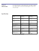
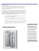
General Information The XL-160 and XL-180 are vacuum insulated, stainless steel containers designed to store, transport, and dispense cryogenic liquid nitrogen. Built to DOT 4L standards, these containers may be used for over-the-road transportation, as well as on-site storage and supply. Specifications XL-160 XL-180 Dimensions (Nominal) Diameter Height 20 in. (508 mm) 57 5/8 (1464 mm) 20 in. (508 mm) 64 3/8 in. (1635 mm) Weight Empty 197 lb. (89 kg) 205 lb. (93 kg) 259 lb. (117 kg) 296 lb.
Handling the Container XL Series containers are very rugged liquid cylinders. All cryogenic liquid containers have an inner container and on outer container with an insulated vacuum space between them; any abuse (dents, dropping, tip-over, etc.) can affect the integrity of the container’s insulation system. When fully loaded, the XL-180 in nitrogen service will contain up to 296 lb. (134 kg) of product. While moving a full container, you may be handling up to 501 lb.
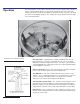
Operation XL-160/XL-180 Component Locations The model numbers of XL-160/XL-180 indicate their respective liquid storage capacities in liters of product. Both cylinders are designed for liquid nitrogen service only. The following component and circuit descriptions are pertinent to either container and should be read before attempting operation. The components may be identified on the Component Location illustration.
Withdrawing Liquid From The Container To use the container in liquid delivery service, attach a transfer hose to the LIQUID connection and open the adjacent LIQUID valve. The pressure in the container will drive liquid product out through the valve as long as the container pressure exceeds trhat of the receiver. The rate of liquid withdrawal from these containers is variable depending on teh container pressure and the saturation temperature of the liquid. With liquid saturated at 22 psig (1.
Filling the Container by Volume 1. Visually inspect the container. Do not attempt to fill containers that have broken or missing components. 2. Connect a transfer hose to the LIQUID fittings from a low-pressure source of liquid. 3. Open the supply valve. Then, on the XL-160/XL-180, open the LIQUID and VENT valves to begin the fill. 4. When liquid begins to spit from the VENT valve, quickly close the LIQUID valve and then the VENT valve. Both valves must be closed before the container relief valve opens. 5.
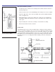
In use, the CGA end fitting on the Fill/Vent Tee Assembly couples to the fill connection to be filled. The Relief Valve vents pressure over 350 psig (24-bar/2413 kPa) that builds up in the fill line due to trapped liquid. The Dump Valve is used to allow the operator to blow-down in the receiving container during a pump fill, or to relieve residual pressure from expanding liquid trapped before disconnecting the fill line. Fill kits are available with different combinations of hose length.
Maintenance Read the Safety Precautions in the front of this manual before attempting any repairs on these containers. Also, follow these additional safety guidelines while performing container maintenance. Never work on a pressurized container. Open the vent valve as a standard practice during maintenance to guard against pressure build-up from residual liquid. Use only repair parts for oxygen service. Be certain your tools are free of oil and grease.
3. Allow the container to stabilize for 24 hours, then weigh it. Record the weight, time and date. 4. Reweigh after the recommended 48 hours. The test if most effective if the container is not moved during this period, and if conducted in an area where ambient temperatures are consistent. NOTE: Fill through the LIQUID valve with VENT valve open. The following calculation will provide the actual Normal Evaporation Rate. Daily NER = Weight Loss (Step 3-Step4) Elapsed Time (Hrs.
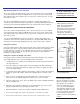
FULL VIEW CONTENTS GAUGE MAINTENANCE WARNING: Cold surfaces should never be handled with bare skin. Use gloves and other protective clothing when performing this procedure. The contents of these containers is measured with the Full View Contents Gauge. The device consists of the gauge assembly beneath a clear plastic protective cover. When the gauge is assembled, a level indicator ring is magnetically coupled to the top of a float rod and moves up or down with the changing level of liquid in the container.
If the rod is turned clockwise (to the left) with respect to calibration nut, the exposed portion of rod becomes longer and the gauge yellow band will be lowered. To raise the yellow band, turn rod counter clockwise. The exposed portion of rod becomes shorter. Once you had adjusted calibration, recheck for proper setting. (See illustration.) After proper setting has been obtained, lock down nut against calibration unit. 1.
CAUTION: When installing the gauge assembly, care must be taken to ensure that the float rod is inserted through “guide ring” located on the liquid withdrawal line inside container. IF gauge does not engage this ring, the contents indication will be inaccurate, or the gauge may be damaged in use. Contents Gauge Insertion Lower the assembly about 4 in. (102 mm) slowly and try to keep the rod in the center of the threaded entrance hole as you do.
Troubleshooting S y m p to m C o n s is te n tly lo w o p e r a tin g p re s s u re . P o s s ib le C a u s e 1 . R e l ie f v a lv e o p e n a t l o w p re s s u re . 2 . C o l d l i q u id . C o r r e c tiv e A c tio n 1 . R e m o v e a n d r e p la c e r e li e f v a l v e . 2 . C o n ta in e r p r e s s u r e w ill b u i ld o v e r t im e , o r a n e x te rn a l p re s s u re s o u rc e c a n b e u s e d to p r e s s u r iz e c o n ta in e r . V e r y lo w o r n o p r e s s u r e show on gauge 1. 2.
Replacement Parts XL-160/XL-180 Component Locations Accessories Accessories available for use with Taylor-Wharton XL Series containers include: · Manifolds, Automatic and Manual · Transfer Hoses · Fill/Vent Tee Assemblies · Container Hand Trucks · Cryogenic Phase Separators For additional information concerning the accessory of your choice, please consult the separate manual on accessories or call Taylor-Wharton at (334) 443-8680.
Index No. 1. 2. 3. 4. 5. 6. 7. 8. 9. 10. 11. * * * * * Description Part No. Gasket, Glass Filled Teflon Float, Contents Gauge Contents Gauge Assembly (Includes Gauge and Spring) Screw, Contents Gauge Cover Cover, Contents Gauge, Protective Gauge, Pressure 0-60 (4.1 bar/414 kPa) Safety Head, 176 psig (12 bar/1213 kPa) Relief Valve, 22 psig (1.5 bar/152 kPa) Ball Valve ½ in. Cross, Brass ¼ in.
Warranty TAYLOR-WHARTON XL Series Liquid Cylinders Taylor-Wharton Gas Equipment Division, Harsco Corporation warrants that each of its Refrigerator and Dewars will be free from defects in material and workmanship, in the normal service for which the product was manufactured, for a period of ninety (90) days from date of shipment to the original purchaser.