
Instruction Manual

2
Installation
1. Remove the necktube cap/core from the Dewar
2. Remove 3 flat-head mounting screws in the base
of the plastic trim collar around the neck of the
Dewar, remove the collar and discard or save for
later. It is not used while the LWD is installed.
3. The liquid withdrawal tube (the longer of the two
plastic tubes) is scored approximately 6 in. (152
mm) from the end. This tube must be shortened
for use with a 25LD or 35LD Dewar by breaking
off the 6 in. (152 mm) section. Discard the 6 in.
(152 mm) piece. The tube is used as supplied with
the 50LD.
4. Insert the longer plastic tube into the underside
of the flange assembly, beneath the LIQUID valve.
Insert the shorter plastic tube into the threaded
fitting on the underside of the flange assembly,
beneath the VENT valve. Tighten the compression
nuts with a wrench to secure.
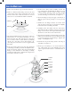
5. Position the safety cable assembly around the
top of the Dewar, underneath the flange. Loosen
V-Band Clamp until the clamp is large enough
to remove from the LWD. Drop the band clamp
around the flange on the Dewar (see Figure 2).
6. Clean the flange 0-ring and apply a thin layer of
silicone grease before placing it on the grooved
flange.
7. NOTE: Be sure flange surfaces are warm, clean
and dry. The 0-ring must be cleaned and lightly
lubricated before installing the LWD.
8. Carefully lower the LWD unit into the Dewar.
The LWD should rest firmly centered on the neck
flange of the Dewar; the liquid withdrawal tube
should not touch the bottom of the Dewar.
9. Place the band clamp around the flange of both the
LWD unit and the Dewar. Be sure that the clamp
is properly engaged on both flanges. Tighten the
clamp — hand tighten only.
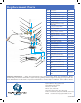
10. Attach the snap of the safety cable to the ring on
the LWD (see figure 2).
11. If the spout assembly is to be used, install it on
the outlet fitting above the LIQUID valve. The
phase separator will ensure a controlled flow of
liquid.
SAFETY
RING
COLLAR
SCREW3
FLANGE
ORING
VBAND
CLAMP
SAFETY
CABLE