
Owner's manual
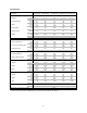

PIPING CIRCUITS
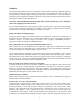
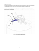
The following paragraphs describe the operation of the piping circuits of the system. The descriptions refer to
the main components of each circuit and are grouped by function. Reference the piping schematic below and
in the general arrangement drawing for the component designations. These component and circuit
descriptions should be understood before attempting operation.
VC-1
C
V-1
F
S
V-1
CV-2
V-5
V
-
4
V-3
V
-
1
LI-1
PI-1
R
-
1
R-2
V-2
SV-1
SV-2
PBC-1
PCV-1
CN-2
CN-1
CN
-
3
CN
-
4
Legend
CN-1 Connection, Liquid Fill / Withdrawal LI-1 Liquid Level Gauge
CN-2 Connection, Full Trycock & Vent PI-1 Pressure Gauge
CN-3 Connection, Pump / Top Fill PBC-1 Pressure Building Coil
CN-4 Connection, Gas Withdrawal VC-1 Vaporizer Coil
V-1 Valve, Liquid Fill / Withdrawal PCV-1 Pressure Building Regulator
V-2 Valve, Full Trycock / Vent SV-1 Safety Valve
V-3 Valve, Gas Withdrawal SV-2 * Safety Valve, 22 psig
V-4 Valve, Pressure Building R-1 Safety Disc
V-5 * Valve, Isolation R-2 Outer Casing Safety Disc
CV-1 Pump / Top Fill Check Valve FSV-1 Fill Stop Valve
CV-2 ** Secondary Pump / Top Fill Check Valve
Notes:
* Featured on DOT models only.
** 500 psi vessels feature a ball valve, ½” FNPT instead of the check valve.
Figure 1: System Piping Schematic
7