
User guide

BT-472 Rev. B
8
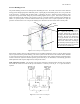
PIPING CIRCUITS
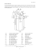
The following paragraphs describe the operation of the piping circuits of the system. The descriptions refer to the main
components of each circuit and are grouped by function. Reference the piping schematic below and in the general
arrangement drawing for the component designations. These component and circuit descriptions should be understood
before attempting operation.
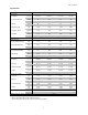
Legend
CN-1 Connection, Liquid Fill / Withdrawal CV-1 Check Valve, Pump/Top Fill
CN-2 Connection, Full Trycock & Vent CV-2 Check Valve, In Line
CN-3 Connection, Pump / Top Fill LI-1 Liquid Level Gauge
CN-4 Connection, Gas Withdrawal VC-1 Vaporizer Coil
V-1 Valve, Liquid Fill / Withdrawal PI-1 Pressure Gauge
V-2 Valve, Full Trycock / Vent PBC-1 Pressure Building Coil
V-3 Valve, Gas Withdrawal PCV-1 Pressure Building Regulator
V-4 Valve, Pressure Building PCV-2 Economizer Regulator
V-5 Valve, Pressure Builder Isolation SV-1** Safety Valve
V-6 Valve, Economizer Isolation SV-2 Safety Valve
V-7 Valve, Low Pressure Isolation SV-3 Safety Valve
V-8 Valve, High Pressure Isolation R-1** Inner Container Safety Disc
V-9 Valve, Pressure Equalization R-2 Outer Casing Safety Disc
V-10 Valve, Manual Ball FSV-1* Fill Stop Valve
*
For use with delivery vehicle equipped with automatic filling system, i.e. Taylor-Wharton
Express Cryogenic Delivery System.
** Option available for Dual Safeties/Rupture Disc with Diverter Valve.
Figure 1: System Piping Schematic