BT-472 Rev. B Express Fill 700 & 1000 Instruction Manual Do not attempt to use or maintain these units until you read and understand these instructions. Refer to the TaylorWharton’s Safety First booklet (TW-202) for handling cryogenic material. Do not permit untrained persons to use or maintain this equipment. If you do not understand these instructions, contact your supplier for additional information.
BT-472 Rev.
BT-472 Rev. B WARNING The following safety precautions are for your protection. Before installing, operating, or maintaining this unit read and follow all safety precautions in this section and in the reference publications. Failure to observe all safety precautions can result in property damage, personal injury, or possibly death.
BT-472 Rev. B parts. Also, be sure all replacement parts are thoroughly "Cleaned for Oxygen Service" in accordance with Compressed Gas Association (CGA) Pamphlet G-4.1 "Cleaning for Oxygen Service" or equivalent industrial cleaning specifications. Observe Safety Codes When Locating Oxygen Equipment Before locating oxygen equipment, become thoroughly familiar with National Fire Protection Association (NFPA) Standard No. 50, "Bulk Oxygen Systems", and with all federal, state and local safety codes.
BT-472 Rev. B Ten percent carbon dioxide in air can be endured for only a few minutes; twelve to fifteen percent soon cause unconsciousness; twenty five percent may cause death if exposure lasts for several hours. Carbon dioxide cannot be detected by the human senses and will be inhaled like air. Carbon dioxide is heavier than air and will accumulate in low lying areas. Carbon dioxide concentrations will be greater in these areas.
BT-472 Rev. B INTRODUCTION This manual provides information for the operation and maintenance of Taylor-Wharton's line of Express Fill 700 and 1000 cryogenic gas supply systems. These products store cryogenic liquid and dispense it as a warm pressurized gas. The Express Fill systems are designed for applications requiring nitrogen, argon, or oxygen gas. These products are ideal for on-site filling with Taylor-Wharton’s Express cryogenic liquid delivery vehicle.
BT-472 Rev.
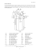
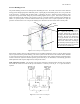
BT-472 Rev. B PIPING CIRCUITS The following paragraphs describe the operation of the piping circuits of the system. The descriptions refer to the main components of each circuit and are grouped by function. Reference the piping schematic below and in the general arrangement drawing for the component designations. These component and circuit descriptions should be understood before attempting operation.
BT-472 Rev. B Fill and Vent Circuits The liquid valve (V-1) communicates with the bottom of the vessel. A stainless steel tag labeled “LIQUID” identifies the valve and the liquid connection (CN-1). Liquid is added or removed from the vessel through this connection and valve. The vent / trycock valve (V-2) is attached to a vertical tube in the upper portion of the vessel. The open end of the tube is positioned at 90% liquid level based on the vessel volume.
BT-472 Rev. B Pressure Building Circuit The pressure building circuit serves to build pressure after filling the vessel. The circuit is also used to ensure sufficient driving pressure during high product withdrawal periods. Opening the pressure building circuit valve (V-4) permits the circuit to function. A stainless steel tag labeled “P.B.” is attached to the valve. When the pressure inside the vessel drops below the pressure builder setting, the pressure building regulator (PCV-1) opens.
BT-472 Rev. B The switch should be set to close at pressure below 125 psi and open after a predetermined pressure rise. To check the setting, vent the container from a pressure greater than 125 psi where the HEATER lamp is off indicating the switch is open and the heater is not receiving power. As the container vents, observe the container pressure gauge. At approximately 125 psi the switch should close and the HEATER lamp will light.
BT-472 Rev. B Economizer Circuit The economizer circuit reduces product loss due to normal evaporation of the liquid within the vessel. The economizer regulator (PCV-2) opens when the pressure within the vessel exceeds the economizer setpoint. The economizer setpoint varies depending on the model. This allows gas from the top of the vessel to flow into the vaporizer circuit. Provided that gas from the vaporizer is being withdrawn for use, the vessel pressure will be reduced.
BT-472 Rev. B Instrumentation Circuits The instrumentation consists of a pressure gauge and differential pressure gauge. The pressure gauge (PI-1) displays the inner vessel pressure in pounds-per-square-inch and kilopascals. The liquid level gauge (LI-1) measures the difference in pressure between the top and bottom of the vessel. Product within the vessel creates a higher pressure at the bottom of the vessel than at the top. Readings on the liquid level gauge are in inches of water.
BT-472 Rev. B INSTALLATION Dimensions and connection data for the Express Fill systems can be found on the General Arrangement Drawings in the appendix of the manual. System installation is the responsibility of the customer. Receiving Inspection Freight and damage claims are the customer’s responsibility. Take time to visually inspect each shipment in the presence of the carrier’s agent before accepting delivery. If any damage is observed, make an appropriate notation on the freight bill.
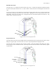
BT-472 Rev. B Vent Line Safety Line . Fill Line Figure 9: Typical fill box installation diagram. Recommended components for a typical fill box installation: Fill Line Vessel Fitting: Compression Fitting, 1/2” Male Pipe Thread x 7/8" O.D. Tube, Brass Tubing: Copper, 3/4" Size (7/8” Actual O.D.), Type K (.065” Wall), per ASTM B-88 Fill Box Fitting: Compression Fitting, 1/2” Female Pipe Thread x 7/8" O.D. Tube, Brass Vent Line Vessel Fitting: Compression Fitting, 3/8” Male Pipe Thread x 5/8" O.D.
BT-472 Rev. B Warning: Lines must not be installed such that they are susceptible to damage. A crushed safety line, for example, could prevent the relief devices from functioning properly. This will cause a dangerous pressure build-up in the vessel and in the lines. Attach the lines to interior walls or secure them to overhead structural members as required by local codes. If damage to the lines is a possibility, the damage prone sections should be placed inside protective jackets.
BT-472 Rev. B OPERATION These instructions are for operators experienced with cryogenic equipment. Before operating this product, become familiar with the safety precautions in this manual and in reference publications. Study this manual and the general arrangement drawing located in the back of this manual thoroughly. Know the location and function of all components.
BT-472 Rev. B Withdrawing Gas To withdraw gas from the Express Fill system, connect a suitable line regulator to the gas withdrawal connection (CN4). Connect the outlet of the regulator to the application. Follow these steps: 1. Open the pressure building valve (V-4). Monitor the pressure gauge (PI-1). When the pressure exceeds the desired delivery pressure, continue. 2. Open the gas withdrawal valve (V-3). 3. Adjust the line regulator to desired delivery pressure.
BT-472 Rev. B MAINTENANCE Routine inspections of the system are recommended. The need for maintenance usually becomes apparent from inspection and indications of improper operation. Typical trouble indications include leakage from valves or piping connections and excessive venting through relief valves. Keep a permanent log of all inspections and repairs performed. Such a log can be valuable in evaluating performance and scheduling maintenance.
BT-472 Rev. B Regulators The pressure building regulator may be adjusted without removal from the system. The following procedure describes the process: 1. Fill the container with liquid product. 2. Open the pressure building valve and allow the container pressure to stabilize for about an hour. Note the pressure. 3. Loosen the lock nut on the adjusting screw on the top of the regulator.
BT-472 Rev. B 1. Leak test joints between the high pressure cylinder regulator and the dump valve. Joints must be leak free before proceeding. 2. Close the on/off valve. Open the dump valve. 3. Open the high pressure cylinder valve. 4. Set the high pressure regulator above the desired set point for the economizer. 5. Slowly open the on/off valve for a few seconds and then close it. 6. When the regulator under adjustment closes, the economizer set point is indicated on the upstream pressure gauge.
BT-472 Rev. B 2. Close the liquid valve and the pressure building valve. Leave the vent valve open for the duration of the test. 3. Allow the container to stabilize for 24 hours after filling. Weigh the container. Record the weight, date, and time. 4. Move the container as little as possible during the test. After 48 hours, weigh the container a second time. Record the weight, date, and time. The following formula will provide the actual normal evaporation rate in pounds per day.
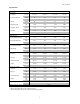
BT-472 Rev. B Trouble-Remedy Guide Trouble 1. Low operating pressure. 2. 3. 4. Excessive system pressure. Leaking relief valve. Ruptured pressure vessel rupture disc. Possible Cause a. Safety valve leaking or frozen open. b. Safety disc ruptured. c. Piping leaks to atmosphere. d. Pressure building / economizer regulator malfunction. e. Excessive product withdrawal. f. g. h. Pressure building valve closed. Malfunctioning pressure gauge. Excessive frost on pressure building coils. a. b. c. d. e.
BT-472 Rev. B Replacement Parts Order replacement parts from Taylor-Wharton Customer Service at 1-800-898-2657. Refer to the piping circuits section on Page 8 to identify the components.
BT-472 Rev.
4075 Hamilton Blvd. Theodore, Alabama 36582 U.S.A. Telephone (251) 443-8680 Fax (251) 443-2250 In U.S. and Canada: (800) TW TANKS (898-2657) P/N 99187836 Publication # BT-472 Rev.