TW-339 easyCarb™ Manual
Keep Equipment area Well Ventilated. Carbon Dioxide can cause asphyxiation by displacing oxygen needed for breathing, resulting in dizziness, unconsciousness, or death. Carbon dioxide cannot be detected by the human senses and will be inhaled like air. If adequate ventilation is not provided, the gas may displace normal air without warning that a life-threatening atmosphere is developing. Store and use carbon dioxide containers only in well ventilated areas.
An automatic pressure building system makes the easycarb™ a self contained gas supply system capable of providing gas at maximum continuous flow rates of up to 10.0 lb./hr. (4.5 kg/hr.) See Specification Chart below for desired EC Model. The easycarb™ is designed to supply gas from the pressurized space that is above the liquid inside the container. If high-demand applications cause the pressure in this space to drop below 125 psig (8.
Planning the Installation Consult with your customer, and check local code restrictions, before determining a location for the unit. The container should be installed in a location away from day to day activity to minimize tampering. It should be accessible for maintenance and occasional monitoring. Note: This container is manufactured to ASME pressure vessel specifications. It should not be used to transport liquid carbon dioxide.
CAUTION: If lifting by crane or hoist, insert hooks in both lifting lug openings on the cylinder ring. Failure to do so could result in container damage or personal injury. Cylinder Handling The easycarb™ cylinder can weigh upwards of 375 lb. (170 kg), but can easily be moved by using a properly designed hand truck. A special Harper cylinder truck (Model ULG 650A) is recommended.
8. Attach the two 90o elbow compression unions to the tubing ends coming through the wall and direct them toward the fill/vent lines. 9. Carefully unload the easycarb™ tank and move it to its permanent position. It is recommended that you securely anchor the top of the container to the wall or building structure with a suitable bracket that clamps the top handling ring.
3. Open the gas USE valve and adjust the outlet regulator – normally to 90 psig (6.2 bar/621 kPa). 4. Tighten the supply line fittings at the use point. FILLING THE CONTAINER Schedule delivery before the container contents drop below ¼ full. This will improve the filling characteristics as well as the gas withdrawal capabilities. 1. Inspect the easycarb™ for proper vent, supply and fill line installation before attempting to fill the container. 2. Check supply container valves to ensure they are open.
Parts Cleaning Before installing, be sure to properly clean any replacement parts that are not packaged and marked for oxygen service. Keep all parts clean during installation to prevent contamination of the carbon dioxide. For more information on cleaning, consult the compressed Gas Association (CGA) pamphlet G-4.1, “Cleaning for Oxygen Service” or equivalent industrial cleaning specifications. Leak Testing After every repair, pressurize the container to about 280 psig (19.
Note: Pressure in the container must be above the desired pressure building setting. Field Adjustment Procedure. For adjustment on the container: 1. Close pressure building isolation valve and use valve. 2. Relieve pressure in the pressure building loop by opening the compression fitting near the pressure building regulator. Note: One-half turn of the adjusting screw will raise or lower the setpoint approximately 35 psig (2.4 bar/241 kPa). 3. Re-tighten fitting opened in step 2. 4.
Checking Container Performance The easycarb™ is basically two containers, one within the other. The space between the containers acts as a thermal barrier because of high technology insulation and a vacuum. Each serves a very important part in the useful life of the container. The insulation is very effective in preventing radiated heat from entering the inner container; the vacuum prevents heat convection or conduction from reaching the liquid contents.
Replacing the Full View Contents Gauge The easycarb™ must be empty of liquid carbon dioxide before attempting to remove the contents gauge, or the contents will solidify. Remove all pressure from container and remove the clear protective cover by removing three (3) screws at its base. Unscrew gauge body using a wrench on the hex fitting at the base of indicator tube. Lift the entire gauge assembly free of the container. The gauge assembly is long and may be very cold.
COMPONENT I.D.
TROUBLESHOOTING Symptom Frost on bottom of easycarb™ Frost on bottom of easycarb™ and Pressure over125 psig (8.6 bar/862 kPa) Frost on easycarb™ and container is noticeably cold over entire outer surface. Low supply pressure Container level gauge shows zero Low supply pressure – easycarb™ pressure OK. Low tank pressure – below 125 psig (8.6 bar/862 kPa) No frost on unit. High carbon dioxide consumption. easycarb™ won’t fill. Possible Cause 1.
TROUBLESHOOTING Symptom Internal easycarb™ Pressure too high – Container won’t fill easycarb™ venting – pressure 270 psig (18.6 bar/1862 kPa). easycarb™ venting – pressure 300 psig (20 to 20.7 bar/ 1999 to 2068 kPa). Possible Cause 1. Customer usage too low. 2. Pressure building circuit improperly adjusted. 3. Customer tank insulation system failure. Relief valve stuck open. 1. Normal relief valve operation. 2. Pressure building circuit not closing. Corrective Action 1.
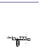
REPLACEMENT PARTS The following replacement parts list is keyed to the accompanying illustrations for parts identification purposes. All replacement parts should be purchased from TaylorWharton. When placing orders, please use the nomenclature and part numbers in this section and send written orders to: Taylor-Wharton 4075 Hamilton Blvd. Theodore, AL 36582 U.S.A.
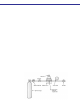
Fill Box Identification Item 1 2 3 * * 6 7 8 Part Number BC04-8C26 BC04-8C35 6812-9412 BC04-8C49 BC04-8C21 6814-9237 BC04-8C45 BC04-8C22 BC04-8C20 * Not Illustrated Description Fill Box, Surface Mount Fill Box, Flush Mount Brass Coupling w/mounting flange Fill Tube Assembly Vent Tube Assembly Elbow, Brass 1/2 in.
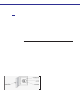
Optional Fill Box Identification Item Part Number 1 BC04-8C26 BC04-8C35 2 6812-9415 3 45702030 4 BC04-8C22 * 7854-6150 * 7854-6155 * Not Illustrated Description Fill Box, Surface Mount Fill Box, Flush Mount Brass Coupling w/mounting flange, Thread to Connect Male Connector, 1/2 in. ODT x 1/2 in. NPT Brass Baffle, Vent Tube Fill Hose Assembly, 15 ft. (4.5 m) Fill Hose Assembly, 6 ft. (1.