
Manual


29
CS SERIES
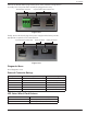
Connect the Remote Alarm plug into the panel at the end of the wiring harness
assembly. This is keyed so that it can only be plugged in one way.
Remote Alarm Connector Cryowire Dual Communication Ports
Figure 15.0
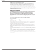
Finally, connect the barrel plug of the power supply and the battery into the
appropriate receptacles in the connector box.
Power Connector Battery ConnectorCryowire Communication Port
Figure 16.0
Diagnostic Menu
Need diagnostic menu
External Connector Ratings
Designated Use Max rated voltage/current ratings Connector type
Power 36 VDC 2.5mm barrel connector
CAN N/A Modular shielded jack
Remote Alarm 300 volts 5mm terminal block
Solenoid Valve 600 volts 4.2mm header
Thermocouple N/A 2 pin thermocouple
Level Sensor 5 amps / contact Sealed circular connector
LED Status Wheel Flash Patterns
Condition LED Flash Pattery
Normal Clockwise pattern, 1 LED per second
General Error Clockwise pattern, rapid rotation, flash