
Manual

26
CS SERIES
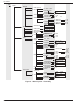
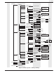
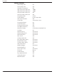
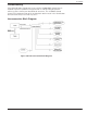
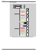
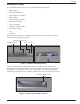
Wiring Diagram
4 wires position 1 P1P1
4 wires position 2 P1P2
10 wires position 1 P2P1
10 wires position 2 P2P2
Blue P1P1 Valve
Red P1P1
Yellow + White/Yellow P2P1 Remote Alarm
Orange + White/Orange P2P1 Remote Alarm
Brown + White/Brown P2P1 Remote Alarm
Yellow/Green P1P1 Power
White P1P1 Power
Harness Control End
White/Black P2P1
Red + Black P2P1 RS-232
White/Red P2P1
Black P2P2
Brown P2P2
Red P2P2 Sensor
Orange P2P2
Yellow P2P2
P2P2
white Power Connector
Yellow/Green
Valve Connector
Red
Blue
White/Bla
ck P2P1 DB-9 Connector
Connector Box End White/Red P2P1
Red + Black P2P1
White/Yellow + Yellow P2P1
White/Orange + Orange P2P1 Remote Alarm Connector
White/Brown + Brown P2P1
Black P2P2
Brown P2P2
Red P2P2 Sensor Assembly
Orange P2P2
Yellow P2P2
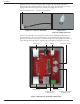
Pod 1
Pod 2
2
1
5
4
3
2
1
3
2
1
6
5
4
3
2
1
P1P1
P1P1
P1P1
P1P1
2
3
5
1
2
3
1
2
3
4
5
Figure 10.0 CS Series Control System Harness Wiring Diagram