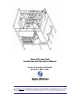
Auto-Fill Laser Pak Installation and Operation Manual Product Part Number AF55-0C00 Revision A, May 8, 2006 Do not attempt to use or maintain these units until you read and understand these instructions. Refer to the TaylorWharton’s Safety First booklet (TW-202) for handling cryogenic material. Do not permit untrained persons to use or maintain this equipment. If you do not understand these instructions, contact your supplier for additional information.
______ Table of Contents WARNING Safety Precautions for Liquid Nitrogen INTRODUCTION System Description Operation Sequence: Brief Overview PIPING CIRCUITS Vent to Bulk Circuits Fill and Vent to Atmosphere Circuits Pressure Building Circuits Use Circuits Safety Devices Instrumentation Circuits INSTALLATION Handling Pre-Installation Checks Customer Installed Equipment/Piping Electrical Power Error Alarm Bulk Tank Pressure Line OPERATION Controller Operation Graphic Terminal Operation First Fill Normal Operati
WARNING The following safety precautions are for your protection. Before installing, operating, or maintaining this unit read and follow all safety precautions in this section and in reference publications. Failure to observe all safety precautions can result in property damage, personal injury, or possibly death. It is the responsibility of the purchaser of this equipment to adequately warn the user of the precautions and safe practices for the use of this equipment and the cryogenic fluid stored in it.
INTRODUCTION This manual provides information for the operation and maintenance of Taylor-Wharton's Auto-Fill Laser Pak cryogenic liquid pressurization system. The Auto-Fill Laser Pak is intended for use in applications requiring nitrogen or argon at pressures higher than possible from standard 175 or 250 psig cryogenic bulk tanks. Cryogenic liquid is supplied to the Auto-Fill Laser Pak from a standard bulk tank. The Auto-Fill Laser Pak “boosts” the liquid up to pressures as high as 450 psig.
3. Once the pressure in vessel A and the bulk tank are nearly equal, gas from vessel A is vented to the atmosphere. Driven by the higher pressure in the bulk tank, liquid from the bulk tank flows into vessel A. Vessel A is in FILLING mode. 4. When vessel A is full, venting to atmosphere stops. Pressure in vessel A is increased by boiling liquid in the pressure builder and returning it to the top of the vessel as gas. Vessel A is in PRESSURIZING mode. 5.
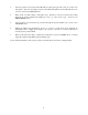
PIPING CIRCUITS The following paragraphs describe the operation of the piping circuits of the system. The descriptions refer to the main components of each circuit and are grouped by function. Reference the piping schematic below and in the general arrangement drawing for the component designations. Round stainless steel tags attached to the system identify the components.
Vent to Bulk Circuits Before filling occurs, the Auto-Fill Laser Pak recovers high-pressure gas in the vessels by returning it to the bulk tank. The gas is vented from the top of the vessel through the vent to bulk solenoid valve (V-2). Gas exits the system through the bulk tank connection (CN-1) and enters the bulk tank through the liquid withdrawal line. The gas is recondensed as it bubbles through the liquid in the bulk tank.
Fill and Vent to Atmosphere Circuits Filling a vessel with liquid from the bulk tank occurs by pressure transfer. The pressure in a vessel is reduced by venting gas from the top of the vessel to the atmosphere through the vent solenoid valve (V-3). A muffler connected to the vent valve outlet keeps noise to a comfortable level. Liquid flows from the bulk tank, through the liquid withdrawal line, and into the system through the bulk tank connection (CN-1).
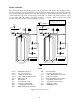
Pressure Building Circuits A pressure building circuit serves to build pressure after filling a vessel. The circuit is also used to ensure sufficient driving pressure during product withdrawal periods. The controller opens the pressure building solenoid valve (V-4) that creates a path from the liquid in the bottom of the container to the gas space in the top. This path contains a pressure-building coil (PB) to vaporize product as it flows from the bottom to the top of the vessel.
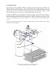
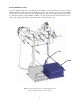
Use Circuits The use circuit delivers pressurized liquid to an external vaporizer for use in the final application. The liquid use solenoid valve (V-1) is opened. Liquid flows out of the vessel, through the liquid use solenoid valve and liquid use check valve (CV-1), and exits the system through the vaporizer connection (CN-2). V-1A CN-2 CV-1A Figure 5: Use circuit for vessel A highlighted in blue. (Frame and wiring omitted from view for clarity.
Safety Devices The system has independent inner container relief devices piped to each of the vessels. Each set consists of a primary relief valve (RV-1) to relieve pressure when it exceeds 600 psig. The valve reseats when pressure drops below this point. In addition, each primary relief valve is supported by a secondary relief device consisting of a rupture disc (BD). The rupture disc will burst at a pressure of approximately 875 psig.
Instrumentation Circuits The system instrumentation consists of liquid level transmitter, pressure transmitter, pressure gauges, and isolation valves. The vessel pressure gauges (PI) display the inner container pressure in pounds-per-squareinch and kilopascals. A pressure gauge is piped to each of the vessels. The liquid level transmitters (PT-1) measure the liquid level in the vessels. This instrument is a differential pressure transmitter.
INSTALLATION Dimension and connection data for the Auto-Fill Laser Pak can be found on the General Arrangement Drawing in the appendix of this manual. System installation is the responsibility of the customer. Handling Employ experienced personnel to move and install the system. Ensure that rigging equipment, if used, has adequate rated capacity to handle the system weight listed in the specifications. This system must be shipped and lifted empty.
Customer Installed Equipment/Piping Designing safe and effective cryogenic systems requires extensive knowledge and experience. Persons lacking the necessary skills are urged to seek competent advice before attempting to design cryogenic systems. Design and consultation services are available from the factory. Contact information is provided at end of the manual. Important: When installing the vaporizer and piping be sure to follow accepted design practices for cryogenic equipment.
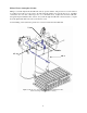
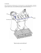
Vaporizer Bulk Liquid Withdrawal Valve Bulk Tank CN-1 Auto-Fill Laser Pak CN-2 Control Panel Strainer Vaporizer Relief Valve Bulk Tank Pressure Line Relief Valve Final Line Regulator To Application Vaporizer ShutOff Valve System Drain Valve To Atmosphere Figure 9: Piping schematic for typical installation Electrical Only persons experienced with industrial wiring should perform the electrical installation.
the front of the control panel disables the alarm. The panel error indictor light will continue to function if the alarm is disabled. A table of alarm conditions is provided in the operation section of the manual. Bulk Tank Pressure Line Installation of a bulk tank pressure line is required for the Auto-Fill Laser Pak to operate. The bulk tank pressure line should be connected to the bulk tank vapor (low pressure) instrument line. This line is also commonly used for the bulk tank pressure gauge.
OPERATION These instructions are for operators experienced with cryogenic equipment. Before operating the Auto-Fill Laser Pak, become familiar with the safety precautions in this manual and in the referenced publications. Make certain all applicable provisions set forth in the Installation Section have been followed before placing an Auto-Fill Laser Pak into operation. Study this manual and the general arrangement drawing located in the back of this manual thoroughly.
Display F1 F2 F3 F4 F5 F6 F7 F8 Scroll 1 2 3 4 5 6 7 8 9 . 0 - Enter Backspace Figure 10: Graphic Terminal TAYLOR-WHARTON A B Bulk Pressure, PSIG 425 410 155 Percent Full 80 50 Vessel Mode View F1 Alarm History F2 Setting Adj F3 Figure 11: Default display screen Six settings are user adjustable through the Graphic Terminal. The initial settings should be used in most cases. However, the settings may be adjusted to better suit a particular installation.
Low Pressure Alarm – If the pressure of the vessel in Supply mode drops below this value the error alarm and error indicator light will be activated. System Vent to Bulk – The system will not vent back to the bulk tank if this parameter is turned off.
Level Scale Vessel Vessel Level Scaled Min. Scaled Max. A 5 0 30 B 8 0 30 Exit F1 Figure 13: Level Scale Screen 6. Each of the vessels should be filled until liquid exits the muffler. When this occurs, note the level displayed on the screen and the vessel letter, A or B. Close the manual override of the vent solenoid valve (V3) for the full vessel. Repeat this step for the other vessel. 7.
3. Close the bulk liquid withdrawal valve. Restart When restarting after a long duration shutdown or if the bulk tank should run empty, the following procedure is recommended. CAUTION: Follow the safety precautions at the beginning of this manual. Accidental contact with liquid or cold gas can occur when operating the solenoid valve manual overrides. 1. Press the start/stop button on the control panel inward. Turn the power switch to the “On” position. Open the control panel door.
Message Meaning Vessel “X” Pressure Low Transmitter “X” Error Vent to Bulk Time Out Fill Time Out Vessel pressure dropped below alarm setting. No signal from transmitter. Vent to Bulk time exceeded 10 minutes. Fill time exceeded 10 minutes. Supply vessel emptied before filling cycle completed for other vessel. Pressurization time exceeded 10 minutes.
MAINTENANCE Routine inspections of the system are recommended. The need for maintenance usually becomes apparent from inspection and indications of improper operation. Typical trouble indications would be error alarms, leakage from valves or piping connections, and excessive venting through relief valves. Keep a permanent log of all inspections and repairs performed. Such a log can be valuable in evaluating performance and scheduling maintenance.
Order replacement parts from the valve manufacturer. Be sure to give all information on the valve nameplate, including the factory part number, to ensure receiving the correct parts for these valves. Atkomatic – Circle Seal Controls Inc. P.O. Box 3300 Corona, California 92878 U.S.A. Phone: 951-270-6200 Fax: 951-270-6201 Web: www.circle-seal.com/atkomatic/ Safety Device Replacement In order to replace the safety devices the system pressure must reduced to zero gauge pressure.
Checking Vacuum This product is carefully designed, manufactured, and tested with every effort made to eliminate vacuum space leakage. An absorbent material (molecular sieve) and a reactive chemical (palladium oxide) are sealed inside the vessel casing to help maintain the vacuum over a long period of time. However, some vacuum deterioration may be experienced after years of service due to out-gassing of materials inside the vacuum space.
Trouble-Remedy Guide Trouble Possible Cause Remedy 1. a. a. Thaw out valve or replace if necessary. b. Replace rupture disc. c. Leak test and repair piping. d. Check fuse and wiring. Clean, seat, rebuild, or replace solenoid valve if necessary. e. Check for leaks downstream. Reduce product use. f. Turn on controller and pull start button. g. Thaw pressure building coils. 2. 3. 4. 5. Pressure low, controller error text “Vessel Pressure Low” or “Pressurization Time Out”. Excessive system pressure.
6. 7. Controller error text, “Transmitter Error”. Controller error text, “Vent to Bulk Time Out”. a. Blown fuse. d. Transmitter damaged or faulty. c. a. Wiring fault. Bulk liquid withdrawal valve closed. Bulk liquid withdrawal line strainer clogged. Vent to bulk solenoid valve (V2) failure. d. c. d. 8. Controller error text, “Fill Time Out”. a. d. c. d. 9. Controller error text, “Filling Error”. Pressure transmitter (PT-2) or bulk tank pressure transmitter malfunctioning.
Replacement Parts Order replacement parts from Taylor-Wharton Customer Service (1-800-898-2657). Refer to system piping schematic on the general arrangement drawing.
APPENDIXES Appendix 1 - Auto-Fill Laser Pak General Arrangement Appendix 2 - Controller, Auto-Fill Laser Pak 29
4075 Hamilton Blvd. Theodore, Alabama 36582 U.S.A. Telephone (251) 443-8680 Fax (251) 443-2250 In U.S.