
Integration Manual

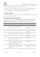


Table Of Contents
- Contents
- 1 System description
- 1.1 Overview
- 1.2 Architecture
- 1.3 Pin-out
- 1.4 Operating modes
- 1.5 Supply interfaces
- 1.5.1 Module supply input (VCC)
- 1.5.1.1 VCC supply requirements
- 1.5.1.2 VCC current consumption in 2G connected mode
- 1.5.1.3 VCC current consumption in 3G connected mode
- 1.5.1.4 VCC current consumption in LTE connected mode
- 1.5.1.5 VCC current consumption in cyclic low power idle mode / active mode
- 1.5.1.6 VCC current consumption in fixed active mode
- 1.5.2 Generic digital interfaces supply output (V_INT)
- 1.5.1 Module supply input (VCC)
- 1.6 System function interfaces
- 1.7 Antenna interfaces
- 1.8 SIM interfaces
- 1.9 Data communication interfaces
- 1.10 eMMC interface
- 1.11 Digital Audio interfaces
- 1.12 ADC interfaces
- 1.13 General Purpose Input/Output
- 1.14 Reserved pins (RSVD)
- 1.15 System features
- 1.15.1 Network indication
- 1.15.2 Jamming detection
- 1.15.3 IP modes of operation
- 1.15.4 Dual stack IPv4 and IPv6
- 1.15.5 Embedded TCP/IP and UDP/IP
- 1.15.6 Embedded FTP and FTPS
- 1.15.7 Embedded HTTP and HTTPS
- 1.15.8 SSL and TLS
- 1.15.9 Firmware update Over AT (FOAT)
- 1.15.10 Firmware update Over The Air (FOTA)
- 1.15.11 Power Saving
- 2 Design-in
- 2.1 Overview
- 2.2 Supply interfaces
- 2.2.1 Module supply (VCC)
- 2.2.1.1 General guidelines for VCC supply circuit selection and design
- 2.2.1.2 Guidelines for VCC supply circuit design using a switching regulator
- 2.2.1.3 Guidelines for VCC supply circuit design using a LDO linear regulator
- 2.2.1.4 Guidelines for VCC supply circuit design using a rechargeable battery
- 2.2.1.5 Guidelines for VCC supply circuit design using a primary battery
- 2.2.1.6 Additional guidelines for VCC supply circuit design
- 2.2.1.7 Guidelines for the external battery charging circuit
- 2.2.1.8 Guidelines for external charging and power path management circuit
- 2.2.1.9 Guidelines for removing VCC supply
- 2.2.1.10 Guidelines for VCC supply layout design
- 2.2.1.11 Guidelines for grounding layout design
- 2.2.2 Generic digital interfaces supply output (V_INT)
- 2.2.1 Module supply (VCC)
- 2.3 System functions interfaces
- 2.4 Antenna interface
- 2.5 SIM interfaces
- 2.6 Data communication interfaces
- 2.7 eMMC interface
- 2.8 Digital Audio interface
- 2.9 ADC interfaces
- 2.10 General Purpose Input/Output
- 2.11 Reserved pins (RSVD)
- 2.12 Module placement
- 2.13 Module footprint and paste mask
- 2.14 Thermal guidelines
- 2.15 Design-in checklist
- 3 Handling and soldering
- 4 Approvals
- 5 Product testing
- 6 FCC Notes
- Appendix
- Glossary
- Related documents
- Revision history
- Contact

TOBY-L3 series - System Integration Manual
TSD-19090601 - R13 System Integration Manual Page 56 of 143
Network searching
Registered the network
Data transfer is on going
Voice call is on going
Mode
Output Status
Remarks
Mode 1
Network indication function is disabled. (Default configuration mode)
Mode 2
Blink slowly (200ms High/1800ms Low)
Network is on searching.
Blink slowly (1800ms High/200ms Low)
The module has registered on the network and work in idle state.
Blink quickly (125ms High/125ms Low)
The module has registered on the network with data transfer is ongoing.
Keep High
The module has registered on the network with voice calling is ongoing.
Mode 3
Low level (light on)
The module has registered on the network.
High Level (light off)
No network coverage or not registered
Mode 4
Blink quickly (100ms Low, 100ms High,
100ms Low then 1700ms High)
No network coverage or not registered
Blink slowly (100ms Low, 1900ms High)
The module has registered on the network.
Table 17: The configuration mode of the network indication pin output
1.15.2 Jamming detection
In real network situations modules can experience various kind of out-of-coverage conditions: limited service
conditions when roaming to networks not supporting the specific SIM, limited service in cells which are not
suitable or barred due to operators’ choice, no cell condition when moving to poorly served or highly
interfered areas. In the latter case, interference can be artificially injected in the environment by a noise
generator covering a given spectrum, thus obscuring the operator’s carries entitled to give access to the
LTE/3G/2G service.
The congestion (i.e. jamming) detection feature can be enabled and configured by the +UCD AT command:
the feature consists of detecting an anomalous sources of interference and signaling the start and stop of
such conditions to the host application processor with an unsolicited indication, which can react
appropriately by e.g. switching off the radio transceiver of the module (i.e. configuring the module in
“airplane mode” by means of the +CFUN AT command) in order to reduce power consumption and
monitoring the environment at constant periods (for more details, see the TOBY-L3 series AT command
manual [2]).
1.15.3 IP modes of operation
IP modes of operation refer to the TOBY-L3 series modules configuration related to the network IP
termination and network interfaces settings in general IP modes of operation are following: