D01132420A RC-F82 Fader Unit OWNER'S MANUAL
ªª For U.S.A. ªª For European Customers TO THE USER This equipment has been tested and found to comply with the limits for a Class A digital device, pursuant to Part 15 of the FCC Rules. These limits are designed to provide reasonable protection against harmful interference when the equipment is operated in a commercial environment.
Contents 1 – Introduction...............................................4 Features................................................................................... 4 Included items...................................................................... 4 About this manual............................................................... 4 Trademarks............................................................................. 4 Precautions for placement and use...............................
1 – Introduction Thank you very much for purchasing the TASCAM RC-F82 Fader Unit. Before connecting and using the unit, please take time to read this manual thoroughly to ensure you understand how to properly set up and connect the unit, as well as the operation of its many useful and convenient functions. After you have finished reading this manual, please keep it in a safe place for future reference. You can also download the Owner's Manual from the TASCAM web site (http://www.tascam.com).
1 – Introduction Precautions for placement and use •• The operating temperature should be between 0°C and 40°C (32°F and 104°F). •• Do not install in the following types of places. Doing so could degrade the sound quality and/or cause malfunctions.
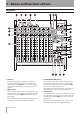
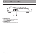
2 – Names and Functions of Parts Top panel 1 SHIFT key This key works just like a shift key on a computer. It works with other keys on the unit that have blue labels. There are two SHIFT keys—one at the top left and one at the bottom right—but they have the same function. 2 INPUT [F1] key Press this key to open the INPUT page of the MIXER SETUP screen on the HS-P82’s color display. Press this key while pressing the SHIFT key to use it as the [F1] function key.
2 – Names and Functions of Parts 5 REMOTE SETUP [F4] key Press this key to open the RC-F82 page of the REMOTE SETUP screen on the HS-P82’s color display. Press this key while pressing the SHIFT key to use it as the [F4] function key. Make function key settings on the RC-F82 page of the REMOTE SETUP screen of the HS-P82 unit. 6 Built-in microphone Use this microphone for talkback. Press and hold the TALKBACK key to activate it.
2 – Names and Functions of Parts o SEL [REC] key (STEREO MIX) Press this key to open the stereo channel setup screen (L/R SETUP page) on the HS-P82’s color display. While pressing and holding the SHIFT key, press this key to enable/disable stereo mix (LR 2MIX) recording. p STEREO MIX knobs (L-R, SOLO) Use these knobs to adjust the master level of the stereo mix. L-R knob This adjusts the master level of both left and right channels at the same time. SOLO knob This adjusts the solo level.
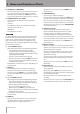
2 – Names and Functions of Parts Rear panel l LINE IN connectors (left and right) These are balanced XLR analog input connectors (1: GND, 2: HOT, 3: COLD). Connect them with the HS-P82 LINE OUT connectors. ; LINE OUT 1 connectors (left and right) These are balanced XLR analog output connectors (1: GND, 2: HOT, 3: COLD). The signals input through the LINE IN connectors (left and right) are passed through and output from these.
2 – Names and Functions of Parts Left side panel b MAIN UNIT connector Use the included cable to connect this unit with the HS-P82 unit’s KEYBOARD connector. n KEYBOARD connector Connect an IBM PC-compatible keyboard with a PS/2 interface to the unit here.
3 – Preparations Connecting with an HS-P82 Using communication functions Use the included cable to connect the MAIN UNIT connector on the left side panel of this unit with the KEYBOARD connector on the HS-P82 unit. If you want to use an external PS/2 keyboard with the HS-P82 unit, connect the keyboard to this unit’s KEYBOARD connector.
4 – Mixer Control Functions This unit has rotary controls and faders for 8 channels. The knobs can be used to adjust one of three parameters: the microphone input level (TRIM), the stereo position sent to the stereo bus (PAN) or the level sent to the stereo bus (LEVEL). The faders can be used to adjust one of two parameters: microphone input (TRIM) or the level sent to the stereo bus (LEVEL). To set this, use the Volume Fader Mode item on the RC-F82 page of the HS-P82.
4 – Mixer Control Functions the HS-P82 unit, the setting will differ from that last made using controls on this unit. Faders Faders can be set to one of two functions. The current setting can be confirmed by viewing the FADER MODE indicators. TRIM (microphone input) This has the same function as the input trim knobs on the front panel of the HS-P82 unit. Choose this setting to adjust the microphone input level.
4 – Mixer Control Functions Function keys You can set each of the [F1] – [F4] function keys as shortcut keys that directly open screens on the HS-P82 unit. Use the Function Key Assign item on the RC-F82 page of the REMOTE SETUP screen of the HS-P82 unit. The setting options are as follows. Press this key while pressing the SHIFT key to use the [F2] function. SETUP [F3] key Press this key to open the SETUP page of the MIXER SETUP screen on the color display of the HS-P82 unit.
5 – Transport Control Functions This unit has transport keys that function in the same way as those on the HS-P82 unit for recording, playback and searching forward and backward, for example. Recording Press the REC key to start recording. Press this key while recording, to stop recording to the current file, but continue recording to a new file without pause. Press the STOP [RETAKE] key to stop recording.
6 – Communication functions With the built-in microphone and headphones connected to the PHONES jack, you can use this unit to communicate with remote crew. To communicate with people using other devices, connect this unit’s LINE OUT 2/TALKBACK connectors to the inputs on devices that you want to communicate through, and connect those devices’ outputs to this unit’s RETURN IN 1 and RETURN IN 2 connectors.
7 – Specifications Inputs and outputs Inputs ªª Analog inputs LINE IN connectors Balanced connectors: XLR-3-31 (1: GND, 2: HOT, 3: COLD) Nominal input level: Dependent on HS-P82 settings Maximum input level: Dependent on HS-P82 settings Pass-through to LINE OUT 1 Pass-through to LINE OUT 2 (when TALKBACK TO LINE OUT 2 switch OFF) RETURN IN connectors Balanced connectors: XLR-3-31 (1: GND, 2: HOT, 3: COLD) Input impedance: 10 kΩ Nominal input level: +4 dBu (1.23 Vrms) Maximum input level: +24 dBu (12.
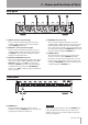
7 – Specifications 260 mm Dimensional drawing 270 mm 63 mm •• Illustrations in this manual may differ in part from the actual product. •• Specifications and the external appearance may be changed without notification to improve the product.
7 – Specifications Block diagram TASCAM RC-F82 19
RC-F82 TEAC CORPORATION Phone: +81-42-356-9143 1-47 Ochiai, Tama-shi, Tokyo 206-8530, Japan www.tascam.jp TEAC AMERICA, INC. www.tascam.com TEAC CANADA LTD. www.tascam.com Phone: +1-323-726-0303 7733 Telegraph Road, Montebello, California 90640 USA Phone: +1905-890-8008 Facsimile: +1905-890-9888 5939 Wallace Street, Mississauga, Ontario L4Z 1Z8, Canada TEAC MEXICO, S.A. de C.V. www.teacmexico.