
- TASCAM DM-3200 Digital Mixing Console Owner's Manual


5 – Channel modules : Global module settings
TASCAM DM-3200 User’s Manual 61
AUX1-2 button (on buss and stereo modules
only), allowing the buss or stereo mix to be routed
through to the aux 1-2 pair (typically for studio fold-
back purposes).
STEREO button (on buss and aux modules only)
allowing you to route the buss or aux send to the ste-
reo buss.
Group assignment displays Display, but do
not allow change on this screen, any fader or mute
group assignments.
NOTE
The buss assignments of channel modules are not
shown on the display, as the appropriate buss assign
indicators light to show the buss assignments when a
channel module is selected.
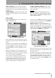
Fader control
From the METER/FADER screens, select either the CH
FADER
or MASTER M/F tabs:
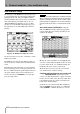
In the channel fader screen shown here, the current
fader and pan positions of all 48 channel modules are
shown.
Moving the cursor around this screen highlights pan
controls or faders in blocks of four (you can also use
the channel
SEL keys to jump around the screen).
Use the four POD encoders to adjust the on-screen
controls.
Mute status and links are also visible on this screen.
Note that in surround mode, the surround L-R pan-
ning is displayed and set here using POD 1 when the
on-screen pan controls are highlighted.
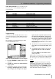
To set a master level in blocks of eight channels,
move the cursor to the bottom right of the screen
(
SETUP) and then use POD 3 encoder to adjust the
fader level. POD 4 selects the group to be set (in
groups of eight channels), or all channels (
ALL).
Press the on-screen
SET button when done. A popup
message asks you to confirm the setting (
ENTER) or
cancel the operation (cursor key).
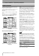
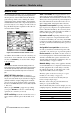
Master screen The MASTER METER/FADER screen
works in a similar way. The top of the screen shows
the buss, aux send and stereo meters (metering points
selected by moving the cursor to
METERING POINT, and
using the wheel and
ENTER to set the point).
Buss and aux levels are selectable in groups of 4, and
the levels can be adjusted as with the channels using
the POD encoders.
The
SETUP section of the screen allows setting of the
first or second eight buss levels, the aux levels, or all
aux and all buss levels, in the same way as for the
channel modules using POD 3 to set the level, and
POD 4 to select the target, with the
ENTER key used
to confirm the setting.
Figure 5.3: Channel fader screen
Figure 5.4: Master fader screen