
- TASCAM DM-3200 Digital Mixing Console Owner's Manual

2 – Basic operational concepts : Encoders
TASCAM DM-3200 Owner’s Manual 21
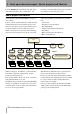
EQ The encoders form four groups of four encoders,
each group controlling a different band, where 1–4
control the low band, 5–8 low-mid, 9–12 high-mid,
and 13–16 high.
Within each band, the first encoder (1, 5, 9, 13) con-
trols gain; the second (2, 6, 10, 14) controls the fre-
quency of the EQ band; the third (3, 7, 11, 15)
controls the Q; and the fourth (4, 8, 12, 16) controls
the band type.
SND AUX 1–2 Encoders 1 through 16 control the
level of the aux send to 1 and 2 from the channel
module immediately under the encoder when aux 1
and 2 are linked. When they are unlinked, they con-
trol the aux 1 send level.
PAN AUX 1–2 Encoders 1 through 16 control the
pan level of the aux send to 1 and 2 from the channel
module immediately under the encoder aux 1 and 2
are linked. When they are unlinked, they control the
aux 2 send level.
LVL BUSS The 16 encoders control the levels of the
correspondingly-numbered busses.
LVL AUX Encoders 1 through 8 control the master
levels of the aux sends.
LVL CH 1–16, 17–32, 33–48 Encoders 1
through 16 control the fader levels of the modules in
the fader layer selected by the
CTRL + ENCODER
key combination.
NOTE
For the BUSS, AUX and CH level settings, the encoders
may be set to control the same modules as the current
fader layer. In this case, turning the encoder will move
the fader, moving the fader will be reflected by the
encoder indicators.
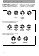
Reading the encoder indicators
The encoder indicators change their pattern, depend-
ing on the parameter being controlled by the encod-
ers.
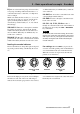
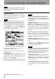
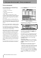
Pan settings When the PAN key is pressed, the
encoders control the panning of the channels/busses
associated with the fader (not in surround modes).
When the encoders are in pan mode, the indicator
patterns are as shown here.
Note how the slight pan away from center half-lights
the indicator at the end of the circle. This helps to
indicate the fact that the pan position is not centered,
even when the line of sight to the center indicator is
blocked by the encoder knob.
Figure 2.11: Encoders in pan mode
Hard left A little less hard
left
Centered A little to the
right