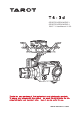
T4-3d SPORTS GOPRO HERO 3 SPORTS GOPRO HERO 4 2015.7.1 User Manual V1.00 Thanks for your purchase of Tarot professional aerial photography products. To ensure your success with this product, we would like to introduce the following information and important notes ,hope it can be useful for you. www.tarotrc.
T4-3d ASSEMBLY SECTION 组装说明书 Contents Warning and Disclaimer . . . . . . . . . . . . . . . . . . . . . . . . . . . . . . . . . . . . . . . . . . . . . 2 Product Introduction、Specifications . . . . . . . . . . . . . . . . . . . . . . . . . . . . . . . . . . . . . 3 I. Product List . . . . . . . . . . . . . . . . . . . . . . . . . . . . . . . . . . . . . . . . . . . . . . 4 II. Mounting & Configuration . . . . . . . . . . . . . . . . . . . . . . . . . . . . . . . . . . . . 5 1.
T4-3d ASSEMBLY SECTION 组装说明书 Warning and Disclaimer Please DO NOT adjust the gimbal or change its mechanical structure! Before leaving the factory, T4-3D gimbal has been adjusted to fit the camera. Based on the setup procedures, you can achieve a fabulous flight experience. Please do not adjust the gimbal or change its mechanical structure. Moreover, do not add any external component to the camera.
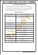
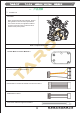
T4-3d ASSEMBLY SECTION 组装说明书 Product Introduction T4-3D a great 3-axis gimbal for model aircraft enthusiasts, can be widely applied to various model aircraft activities and entertainments. With unique internal wiring design, built-in IMU gimbal control module, specialized servo drive module, this gimbal is able to support Pan Follow (PF) mode and First Person View (FPV) mode. Moreover, video out and battery charging of GoPro Hero 3 can be achieved through T4-3D.
T4-3d ASSEMBLY SECTION 组装说明书 一. 产品清单 1. Product List Gimbal * 1 With unique internal wiring design, built-in IMU gimbal control module, specialized servo drive module, this gimbal is able to support Pan Follow (PF) mode and First Person View (FPV) mode.
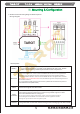
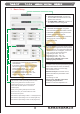
T4-3d ASSEMBLY SECTION 组装说明书 II.Mounting & Configuration 1.Gimbal Controller Wiring Diagram & Descriptions Wiring Diagram Descriptions: Battery Receiver Power Supply:3S-6S Li (11V-26V) * If you choose a battery to power up the gimbal and multi-rotor, please make sure this battery meets requirements of both components. 1.Conventional Receiver: connect it to the CH1/SBUS and CH2 Channel in the gimbal main controller. Also, set Receiver Type and corresponding channel in the assistant software. 2.
T4-3d ASSEMBLY SECTION 组装说明书 2. Gimbal Working Mode You should select a three-positioned or two-positioned switch in R/C for working mode. Please connect the corresponding port of the receiver to CH1/SBUS or CH2 of the gimbal controller. Also, set RC MAPPING in the assistant software. For different positions, use endpoint fine tune function to set. Please refer to the MODE Channel section in assistant software for detailed information.
T4-3d ASSEMBLY SECTION 组装说明书 III.Flight Test Steps: 1. Please ensure all the wirings are correct and the power supply is in great condition. 2. Turn on the transmitter. 3. Powering up the gimbal and keep it still. After self-check, gimbal angle corresponds to INIT ANGLE in the assistant software. 4. Switch from different working modes to check the rotation direction in ROLL, PITCH, and PAN axis. Attentions: Before flight test, please ensure: 1 .
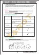
T4-3d ASSEMBLY SECTION 组装说明书 3. Basic Setup Methods to Connect the Receiver: 1. Conventional Receiver: connect it to the CH1/SBUS and CH2 Channel in the gimbal main controller. 2. FUTABA SUBS or SBUS-2: connect it to CH1/SBUS channel in the gimbal 1. Receiver Unconnected: set gimbal mode in Default Mode of assistant software. 2. Receiver Connected: set gimbal mode in MODE channel of the receiver.
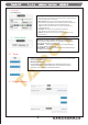
T4-3d ASSEMBLY SECTION 组装说明书 4. Channels (1)RC Mapping Tilt Channel Push the stick, and observe the rotation direction of the gimbal and the moving direction of the cursor Mode Channel:This channel controls gimbal working mode. Choose a three-positioned or two-positioned switch to control the working mode of the gimbal. Map it into Mode Channel. Toggle the switch to the position, the cursor should be in the corresponding area.
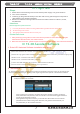
T4-3d ASSEMBLY SECTION 组装说明书 Update Procedures: ( 1)Please make sure the connection between gimbal control module and PC are correct, and check whether or not the module version can be seen. ( 2)Please connect the DATA/FC of module and PC through a USB cable ( 3)Click for upgrade. Wait until all the procedures have been done. Attention: If something wrong occurs during update, please check the connection and power supply. Also, make sure you have correctly installed the drive program.
ASSEMBLY SECTION T4-3d 组装说明书 VII. LED Indicators Gimbal Main Controller LED Indicators Status RED & BLUE lights blink twice. RED & BLUE lights are constantly on. BLUE light turns off. POST (Power On Self-Test) Status. POST (Power On Self-Test) fails. Flight Controller Disconnects. BLUE light is constantly on. BLUE light blinks. Flight Controller Connects. Flight Controller connects and flight data are available. 1. Line Fault. RED light blinks. 2. Gimbal stall protection goes far beyond ten times.