
Installation guide


10
the thermostat inputs to the unit. Thus, when the
switch opens and then closes, there will be a 5
minute short cycling delay before the outdoor
unit will energize.
High-Pressure Switch — A high-pressure
switch is factory-installed and located in the
compressor discharge line internal to the outdoor
unit. The switch is designed to de-energize the
system when very high pressures occur during
abnormal conditions. Under normal conditions,
the switch is closed. If the discharge pressure
rises above 575 psig, then the switch will open
and de-energize the outdoor unit. The switch
will close again once the discharge pressure
decreases to 460 psig. Please note that the switch
interrupts the thermostat inputs to the unit. Thus,
when the switch opens and then closes, there
will be a 5 minute short cycling delay before the
outdoor unit will energize.
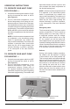
Short Cycle Protection — With the system
operating in COOLING mode, note the setpoint
temperature setting of the thermostat, and
gradually raise the setpoint temperature until
the outdoor unit and indoor blower de-energize.
Immediately lower the setpoint temperature of
the thermostat to its original setting and verify
that the indoor blower is energized and that the
outdoor unit remains de-energized. Verify that,
after approximately 5 minutes, the outdoor unit
energizes and that the temperature of the air
supplied to the facility is cooler than ambient
temperature.
Comfort Alert
TM
Diagnostics (Select Models)
— The Comfort Alert
TM
diagnostics module
facilitates troubleshooting heat pump and air
conditioning system failures. This Comfort
Alert
TM
module is designed only for single-phase
systems with scroll compressors that have
internal overload protection. By monitoring and
analyzing data from the compressor and the
thermostat demand, the module can detect the
cause of electrical and system related failures
without any sensors. A flashing LED indicator
communicates the ALERT code and guides the
service technician more quickly and accurately
to the root cause of a problem.
NOTE: This module does not provide safety
protection! The Comfort Alert
TM
module is a
monitoring device and cannot control or shut
down other devices.
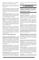
LED Description (See Figure 2)
POWER LED (Green): indicates voltage is present
at the power connection of the module.
ALERT LED (Yellow): communicates an
abnormal system condition through a unique
flash code. The ALERT LED will flash a number
of times consecutively, pause and then repeat
the process. The number of consecutive
flashes, defined as the Flash Code, correlates
to a particular abnormal condition. Detailed
descriptions of specific ALERT Flash Codes are
shown in Table 1 of this manual.
TRIP LED (Red): indicates there is a demand
signal from the thermostat but no current to the
compressor is detected by the module. The TRIP
LED typically indicates the compressor protector
is open or may indicate missing supply power
to the compressor.
The scroll compressor’s run (R), common (C)
and start (S) wires are routed through the holes
in the Comfort Alert
TM
module marked “R,” “C”
and “S.”
24 VAC Power Wiring — The Comfort Alert
TM
module requires a constant nominal 24 VAC
power supply. The wiring to the module’s R and
C terminals must be directly from the indoor unit
or thermostat.
The Comfort Alert
TM
module requires a thermostat
demand signal to operate properly.
NOTE: After the thermostat demand signal is
connected, verify that 24 VAC across Y and C
when demand is present.
TROUBLESHOOTING
Interpreting The Diagnostic LEDs – When
an abnormal system condition occurs, the
Comfort Alert
TM
module displays the appropriate
ALERT and/or TRIP LED will flash a number of
times consecutively, pause and then repeat the
process. To identify a Flash Code number, count
the number of consecutive flashes.
Every time the module powers up, the last
ALERT Flash Code that occurred prior to shut
down is displayed for one minute. The module
will continue to display the LED until the condition
returns to normal or if 24 VAC power is removed
from the module.
Cooling — Gradually lower the thermostat
temperature setpoint below the actual room
temperature and observe that the outdoor unit
and indoor blower energize. Feel the air being
circulated by the indoor blower and verify that it is
cooler than ambient temperature. Listen for any
unusual noises. If present, locate and determine
the source of the noise and correct as necessary.