
User manual

R e p l a c i n g t h e E m i t t e r
If you are in any doubt about following the procedure below, please contact us for technical assistance. The mains power should be
disconnected before any attempts are made to replace the emitter. The following should be carried out with compliance to the latest IEE
regulations. If you are unfamiliar with installing such fixtures, contact a qualified electrician to carry out. Please read the notes on page 5
with regards to handling and buying a replacement emitter before proceeding.
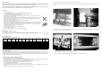
1. Ensure the heater and emitter are cool and the power supply is disconnected by removing the plugs from the socket outlet - both plugs must be
removed even if only one emitter is to be replaced.
2. Remove the screws from the terminal box at the back of the emitter you wish to replace and lift off the lid - see Fig. G.
3. Disconnect the emitter from the connector blocks by unscrewing the screws highlighted above in Fig. H and remove the white coloured emitter wires
from the terminal block.
4. At the back of the heater, remove the plate holding the terminal box by removing the two fixing screws as shown in Fig. J.
Fig. G Fig. H
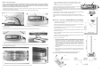
5. Pull the emitter wires one at a time through the plate to remove as shown in Fig. K.
6. At the front of the heater, the guard in front of the emitter you are replacing should be removed by gently pulling it away from the heater so it prises
out of its locating holes at each end (Fig. L).
Fig. J
7. Remove the screw (Fig. M) from the side reflector and lift it up away from the heater to remove it.
Fig. L
Fig. M
Fig. K
6
M o u n t i n g - I n d i v i d u a l Unit (Wall Mounting or Chain Hanging)
•
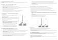
The Sorrento IP Double heater should only be wall mounted in a horizontal manner or hung from
a ceiling from chains (not supplied).
•
When wall mounting the Sorrento IP Double heater in a horizontal manner, do not position the
heater at an angle more than 90° and less than 30° as shown in Fig. A.
•
When ceiling hanging the Sorrento IP Double heater, ensure the minimum distance from the
ceiling is adhered to as shown in Fig. B.
•
Always allow the heater to cool before attempting to reposition/move. Never attempt to move the
heater while it is switched on!
•
Observe the minimum safe distance between the heater body and inflammable surfaces and
objects when mounting.
•
Please refer to Table 1 for the recommended positioning of the heater with regards to minimum
distances. Do not install the heater in a corner!
•
Keep out of the reach of children.
1. When wall mounting, securely fasten the L-shaped wall brackets to the mounting surface
using both of the fixing holes in the short part of the bracket (see Fig. D for mounting hole
centres). Please refer to Table 1 for recommended positioning of the heater. Please note.
Wall fixings are not supplied. They should be selected to substantially support the
weight of the installation. If in doubt contact a professional for advice! When hanging from
a ceiling two equal length and gauge chains are required and should be selected with fixings
that are more than adequate to hold the weight of the heater. Again, if in doubt contact a
professional for advice!
2. The heater should be mounted with the terminal box at the bottom of the heater when being
wall mounted.
3. When wall mounting, fix in the required angular position by tightening the fixing bolts on the
brackets at the rear of the heater as shown in Fig. C. The heater should face directly down
when hanging.
4. Secure the supply cable so it is not resting on the body or obstructing the air-vents.
Always isolate the heater from the mains supply when adjusting the position.
Fig. A
Fig. C
Fig. B
Fig. D
When the electrical connection is outside, it is recommended that a waterproof socket is
used for the connection/terminal. Otherwise, the plug should be connected to a socket
indoors.
If in any doubt, please contact a suitably qualified electrician.
1. Unscrew the terminal box cover at the back of the heater and feed the supply cable
through the compression gland ensuring the rubber seal is on the cable.
2. Use a minimum of 1.0mm
2
H05RN-F supply cable with 2 poles and earth and sleeve with
silicon glass fibre braided (250°C) Sleeving. The live and neutral wires must be connected
to the terminal block. See Fig 1.
3. The green/yellow wire should be connected to the clamp marked with the earth symbol using a
suitable wire terminal. Fit cord grip and terminal box saddle once wired.
4. Tighten the barrel nut of the compression gland so that the rubber seal grips the cable (Fig 2).
5. Ensure that the cover is secured well by hand tightening all for screws evenly to prevent water
ingress.
3
N
Fig. 1
Fig. 2
E
L