
User manual

W A R N I N G : R i s k o f F i r e
Keep combustible materials such as furniture, papers, clothes and curtains at least 1.8m (6 feet) from the front of the heater and away
from the sides and rear. If the heater is to be used outside, we recommend that a waterproof or indoor socket is used.
I n t r o d u c t i o n
The Sorrento IP Double heater produces radiant heat like the sun, warming people and objects rather than the air in between. It is mounted on an
adjustable bracket that allows the heat to be directed exactly where it is required. Its attractive, lightweight design means that it is effective yet
unobtrusive. The Sorrento IP Double heater is designed for indoor and outdoor use so is therefore weatherproof.
Please read the following instructions carefully before use. The safety of this heater is guaranteed only by its correct usage in accordance
with these instructions, therefore it is recommended that they are retained for future reference.
S p e c i f i c a t i o n
T a b l e 1 . U K a n d E u r o p e a n H e a t e r s
Use MCB Type 3.
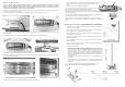
C o n f i g u r a t i o n s
The Sorrento IP Double heater is a single unit that contains two emitters. It can be installed as an individual unit or joined to one or two more single
units. It is supplied with joining bars that connect the heaters together to increase the size and output of the installation. The maximum number of
individual units that can be joined together is three (long joining bars required – available separately). Please read the section ‘joining individual
heaters together’ for information on how this should be done.
No. of Units Voltage No. of Emitters Total Current Total Min. height Min. dist. Min. dist. Dimensions (inc. Weight Ingress
x (Volts) x Power Power (A) per Current (A) from floor from ceiling from side bracket & bars max. (kg) Protection
Model Type
(Watts) (Watts) emitter of unit (m) (m) wall (m) pos.) W x H x D (mm)
(IP)
1 x SOR 210IPD 230 2 x 1000 2000 4.3 8.7 2.5 0.5 1.0 790 x 228 x 323 5.6 IP24
1 x SOR 215IPD 230 2 x 1500 3000 6.5 13.0 3.0 0.5 1.0 790 x 228 x 323 5.6 IP24
1 x SOR 220IPD 230 2 x 2000 4000 8.7 17.4 3.5 0.5 1.0 790 x 228 x 323 5.6 IP24
2 x SOR 210IPD 230 4 x 1000 4000 4.3 17.4 3.5 0.5 1.0 790 x 460 x 142 11.2 IP24
2 x SOR 215IPD 230 4 x 1500 6000 6.5 26.1 4.5 0.5 1.5 790 x 460 x 142 11.2 IP24
2 x SOR 220IPD 230 4 x 2000 8000 8.7 34.8 4.7 0.5 1.5 790 x 460 x 142 11.2 IP24
3 x SOR 210IPD 230 6 x 1000 6000 4.3 26.1 4.5 0.5 1.5 790 x 693 x 142 16.8 IP24
3 x SOR 215IPD 230 6 x 1500 9000 6.5 39.1 5.0 0.5 1.5 790 x 693 x 142 16.8 IP24
3 x SOR 220IPD 230 6 x 2000 12000 8.7 52.2 5.0 0.5 1.5 790 x 693 x 142 16.8 IP24
I n s t a l l a t i o n - A l l C o n f i g u r a t i o n s
Warning - this appliance must be connected to an earthed supply.
The wired versions (210/UK, 210/EU, 215/UK, 215/EU, 220UK & 220EU) are fitted with 5.0 metres of supply cable and a moulded plug, therefore it
is unnecessary to remove the terminal box in order to carry out normal installation of these models.
All unwired versions (210, 215 & 220) should be installed by a suitably qualified electrician, following the instructions below.
All installations must be in accordance with the latest I.E.E safety regulations or equivalent.
We recommend using a RCD where applicable.
If self wiring, a large double pole switch with a 3.0mm contact disconnection should be fitted.
If the supply cord becomes damaged, it must be replaced by the manufacturer, its service agent or a similar qualified person in order to avoid a
hazard.
Please observe the minimum safe distance between the heater body and any inflammable surfaces.
C a u t i o n
Before using this appliance:
- Check that the voltage indicated on the type plate corresponds to the mains supply voltage.
- Ensure that the heater has been securely fastened in its final mounting position.
Do not locate the heater immediately below a socket outlet.
Remove the plug from the mains socket (or disconnect pole switch) during installation, cleaning and/or replacing the emitter
and always ensure that the emitter is cool.
Do not handle the quartz emitter with bare hands. If it is inadvertently touched, remove finger marks with a soft cloth and
methylated spirit or rubbing alcohol. Otherwise, the marks will burn into the quartz glass causing premature heater failure.
Do not use an extension cable with this product.
Keep the mains cable away from the body of the heater which will get hot during use.
Do not cover or obstruct the heater while it is in use.
This appliance is not intended for use by persons (including children) with reduced physical, sensory or mental capabilities,
or lack of experience and knowledge, unless they have been given supervision or instruction concerning use of the appliance
by a person responsible for their safety. Children should be supervised to ensure that they do not play with the appliance.
Do not insert any object through any slot or opening in the heater.
Do not use if guard is not present.
Do not install less than the minimum mounting distance from the floor.
Do not use the heater in a bathroom.
Warning - this appliance must be connected to a supply that is earthed!
2
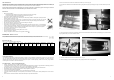
8. Remove the screws from both sides of the middle reflector and lift it up to remove it (Fig. N).
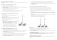
9. The emitter can be released from the middle emitter holder by prising back the spring clip and lifting up enough to clear the released clip as shown
in Fig. P.
11. The emitter should now be removed from the heater as shown in Fig. R.
12. Refit new emitter(s) in reverse order ensuring that no wires get trapped and all screws are fully tightened.
Fig. N
7
10. At the opposite end of the emitter the wire should be pulled out of the side slot and the emitter can be lifted up completely (Fig. Q). The wires should
be gently pulled so they come out from behind the reflector.
Fig. R Fig. Q
Fig. P