
Operation Manual


5
2. Mounting
Isolator User manual rev 1.0.0
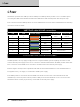
2. Mounting
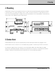
ISOLATOR is housed in a strong galvanised steel case that can be mounted using 4mm diameter hardware
in the holes that are on 40mm x 92.5mm centres. If dust or moisture resistance is required then it will be
necessary to mount ISOLATOR in a suitable enclosure. Note that the case of ISOLATOR is connected to the
earth system on the LINK side of the isolation barrier.
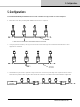
The DATA & Ground (S) of all
IN & OUT connectors are
internally inter-connected
SAB
IN OUT
SAB
AES3 in to out
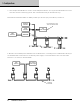
+
connector on product
ISOLATED SUB-NETWORK
Ext PSU
AES3 link to out
NETWORK BACKBONE
-
DATA terminated
ABS
LINK
to
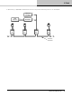
3. Connections
ISOLATOR has three ports: IN; OUT & LINK. Each port has both RJ45 and ‘Phoenix’ pluggable screw
terminal blocks. These connectors are connected directly together so either may be used as convenient.
For example it might be most convenient to connect ISOLATOR ‘LINK’ to the LINK output of a VNET
deviceusing a standard RJ45 patch lead while using the Phoenix connections for the hard wired network
‘backbone’ cabling on the IN and OUT ports (which are also connected directly together).