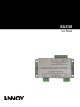
ISOLATOR User Manual
ISOLATOR User manual rev 1.0.
Table of Contents Table of Contents Page 1. Introduction............................................................................................................................. 4 2. Mounting..................................................................................................................................5 3. Connections.............................................................................................................................5 4. Power ................................
1. Introduction 1. Introduction ISOLATOR has been designed to ease the problems often presented when large VNET systems are constructed.
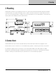
2. Mounting 2. Mounting ISOLATOR is housed in a strong galvanised steel case that can be mounted using 4mm diameter hardware in the holes that are on 40mm x 92.5mm centres. If dust or moisture resistance is required then it will be necessary to mount ISOLATOR in a suitable enclosure. Note that the case of ISOLATOR is connected to the earth system on the LINK side of the isolation barrier.
4. Power 4. Power ISOLATOR is powered via its LINK port. As the LINK port on VNET products provides a source of suitable power, connecting the LINK of ISOLATOR to the LINK of the VNET device with an RJ45 patch cable will power it up.
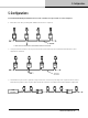
5. Configurations 5. Configurations For maximum flexibility ISOLATOR can be used in a number of ways, below are some examples : 1. Basic IN to OUT daisy-chaining with additional branches as required LINK LINK LINK LINK LINK LINK LINK LINK ISO IN ISO IN OUT ISO IN OUT ISO IN OUT OUT NETWORK 'BACKBONE' 1. Basic IN to OUT daisy-chaining with additional branches as required 2.
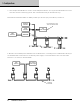
5. Configurations 4. Here multiple ISOLATORS are used to create multiple backbones. As long as the ISOLATORS are local to each other and the controlling system, then each backbone may be the full 1km long. Note that the maximum number of VNET products per network (not per backbone) remains 32.
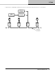
4. Power 6. Both Tannoy’s SENTINEL and Ethernet interface can provide sufficient power for one ISOLATOR Ethernet Interface USB Interface LINK IN LINK LINK LINK LINK ISO IN SENTINEL OUT ISO IN OU T LINK LINK LINK LINK ISO IN OUT LINK ISO IN OUT NETWORK 'BACKBONE' Isolator User manual rev 1.0.
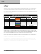
6. Technical specifications 6. Technical specifications Performance Maximum voltage between LINK and IN / OUT 1kV AC or DC Data protocol and format Linea OSNET over VNET Maximum length of IN / OUT CAT5 backbone cable 1000m Power requirement 12V DC <100mA Environmental protection IP40 Weight 0.15 kg Dimensions 102 mm x 52 mm x 24 mm . 10 ISOLATOR User manual rev 1.0.
7. Notes 7. Notes Isolator User manual rev 1.0.
6481 0702 / 091215 tannoypro.com Tannoy operates a policy of continuous research and development. The introduction of new materials or manufacturing methods will always equal or exceed the published specifications. All specifications are subject to change without notice. Copyright (c) 2015 Music Group Innovation SC Ltd. All rights reserved.