user manual
SAFETY WARNING This equipment is designed for permanent installation. Disconnection from the mains supply is to be achieved by isolation of the circuit to which it is connected. Do not remove any covers, loosen any fixings or allow items to enter any aperture. Objects filled with liquids should not be placed on this apparatus. The rear of this product can get hot. Avoid direct skin contact during operation and for at least 5 minutes after power has been isolated.
IMPORTANTES INSTRUCTIONS RELATIVES A LA SECURITE 1 2 3 4 5 6 7 8 Lire ces instructions. Conserver ces instructions. Tenir compte de tous les avertissements. Respecter toutes les instructions. Ne pas utiliser cet appareil a proximité d’eau. Ne nettoyer qu’avec un chiffon sec. Ne bloquer aucune ouverture de ventilation. Installer en suivant les instructions du fabricant.
CONTENTS 1 INTRODUCTION 2 UNPACKING 3 SOFTWARE INSTALLATION & SETUP 3.1 BeamEngine Programme 3.2 MatLab Runtime Library MCR 3.3 QFlex BeamEngine Application 3.4 Updates 3.5 Uninstalling 4 INSTALLING THE MATLAB RUNTIME LIBARARY 5 INSTALLING THE BEAMENGINE APPLICATION 6 USING BEAMENGINE 7 8 USING VNET SOFTWARE (PODWARE) 8.1 Overview 8.2 Layout 8.3 Menus 8.4 Toolbar 8.5 Communications 8.6 Launching a Panel 8.7 Controlling Devices – a quick overview 8.8 Parameter Synchronisation 8.
9 10 HARDWARE CONFIGURATION (GENERAL INFORMATION) ASSEMBLY INSTRUCTIONS 10.1 QFlex 8 & QFlex 16 Assembly 10.2 Wall Bracket Mounting Centres - QFlex 8 & QFlex 16 10.3 QFlex 24 & QFlex 32 Assembly 10.4 Wall Bracket Mounting Centres - QFlex 24 & QFlex 32 10.5 QFlex 40 Assembly 10.6 Wall Bracket Mounting Centres - QFlex 40 10.7 QFlex 48 Assembly 10.
1 INTRODUCTION Congratulations on the purchase of your new QFlex loudspeaker. QFlex is a range of self powered, digitally steerable loudspeaker arrays. With state of the art algorithms and dense physical spacing of transducers, QFlex is the first product of its kind to realize full range beam steering capabilities, producing class leading performance for both vocal and music applications. To avoid shipping very long products, it will be possible to assemble the components of a QFlex column on site.
3.1 BEAMENGINE PROGRAMME There are two programme modules to install. For both the installation is fully automatic. However, please note the following:Initialization time: Due to large data-files the installation may need a considerable time to load. Also, on the very first run of QFlex BeamEngine the MatLab Library needs to initialize, which cause a short delay. Windows Vista: Do not install QFlex BeamEngine to the standard folder but elsewhere, for instance C:\Tannoy\QFlex\.
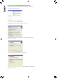
4 INSTALLING THE MATLAB RUNTIME LIBARARY Having downloaded the software, double click on the MCRInstaller_v77.
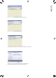
Approve the suggested file location by clicking on ‘Next’ Click on ‘Install’ to begin the Installation The installation will begin. Due to the file size this may take some time Click ‘Finish’ to complete the installation. There is no need to start this programme as it resides behind the BeamEngine programme. It will no longer be visible.
5 INSTALLING THE BEAMENGINE APPLICATION Having downloaded the software, double click on the QFlex_vXXXX.exe The following window will appear. The QFlex Setup wizard will start; click ‘Next’ to continue Accept the terms of the licence agreement to continue with the installation. Click ‘Next’ to continue. Approve the suggested file location by clicking on ‘Next’ If you would like the setup programme to create a desktop icon check the box. Click ‘Next’ to continue.
Click on ‘Install’ to begin the Installation Check ‘Launch QFlex’ if you wish to begin using the software immediately. Click ‘Finish’ to complete the setup.
6 USING BEAMENGINE Click on the QFlex icon which the installer left on your desktop. On the very first run of the program you will be prompted to select your preferred units of measurement. These settings can be modified at any time in the menu options.
6.1 MENU (File, Edit, Processing, Options, Help) File From here you can create a new project, open an existing and save a project. A BeamEngine project has the file extension (.qfl) Save a Beamsteering File (.bef) Save a 3D Balloon file (.xhn) for export into acoustical simulation programmes. Print a detailed project sheet. This includes Parameters, Project Notes & graphs. ‘Export’ generates a screenshot of your current project (.
Units Tab Verify that you are using the correct measurement units Misc Tab By checking this box a shadow will be cast behind venue planes if they are raised above floor level Help Here you will find programme info, including version number and a copy of this user manual in PDF format. The first step is to select your QFlex model, using the BeamEngine software is a simple and effective way of selecting the correct model.
6.2 LAYING OUT VENUE PLANES 1. Click on ADD to create a new venue plane(s) 2. Choose SPL to target this particular area from the loudspeaker. NB. Other Options here are Silent – This is basically a probe to view the out of beam attenuation on the SPL map. Don’t Care - In the straight forward default case the steering algorithm will aim for silence in all unspecified directions, the user can specify areas where avoiding areas does not matter, for example, areas of high absorption.
Note: Longer arrays will have better low frequency control characteristics 10. Set the height of the loudspeaker. The specified height is to the bottom of the array. Hint: QFlex will invariably be installed in architecturally sensitive environments.The client or architect will most probably impose restrictions on preferred mounting locations. Beware of mounting the loudspeaker too low. The venue will most probably be empty when you demo or commission the project.
6.4 ADDING ADDITIONAL VENUE ITEMS 1. Here we have added a second venue plane, in this case a balcony. BeamEngine will automatically target the second venue plane (no need to specify opening angles or steering angles). Note that the intensity of the second beam has been manually increased to mach the SPL of the first venue plane. Both beams can be independently manipulated in this way. Additional venue planes can be added as necessary. 2.
6.5 PROBES 1. Click on the small grey box shown. Drag the line on the SPL key to draw the isobar into the display. The isobar corresponds to the position on the SPL graph. 2. Click on the small grey box shown. Here you can drag and drop the crosshairs shown. Their corresponding co-ordinates and SPL are shown directly below the SPL map. 3. Click on the small grey box shown. Drag the blue probe horizontally across the SPL graph. The SPL across each venue plane is shown at 3a. 6.
6.7 BALLOON DATA EASE™ and CATT Acoustic™ Where more than one QFlex array is deployed in an installation it may be necessary or demanded to carry out a more resolute acoustical analysis of the room. To properly evaluate QFlex coverage in 3D you can export a configuration file from BeamEngine which can be used in Ease™ and CATT Acoustic™ Click on the ‘Balloon File’ tab. The name of the file automatically defaults to the QFlex model you are using. In this case ‘QFlex32.xhn’ This name can be modified.
6.8 BEAMENGINE – FREQUENTLY ASKED QUESTIONS Q. If I’m adjusting Master Beta, what LF driver utilization compromises do I suffer in adjusting to less than “1”? A. Master multiplication factor to apply to regularization factors beta given in global A.wf(woofer) and A.tw(tweeter). Normally masterbeta = 1, but it can be reduced to 0.1, trading some SPL for sharper directivity at the lower end of each sub-array’s (tweeter or woofer) working range. The default settings will be fine in almost all applications. Q.
7 INSTALLING VNET SOFTWARE (PODWARE) The latest version of Podware can be found at www.tannoy.com. Any new updates will automatically overwrite any existing versions. 1. Having downloaded the software, double click on the ‘Setup.exe icon. The welcome screen will appear. Click 2. Select your destination Folder. Click 3. Confirm Installation. Click 4. If you accept the licence agreement check ‘I Agree’ and Click 5. The programme will begin installing 6.
8 USING VNET SOFTWARE (PODWARE) Podware is a software package running under PC WindowsTM for setting up and controlling any Tannoy VNET device. It is a clean Object Oriented package using the latest development technologies yielding intuitive ease of use and all the features you have come to expect and more. Podware is used for configuring installations as well as the live control and monitoring of devices during use. These devices may be connected individually using RS232 or USB.
8.
8.4 TOOLBAR The toolbar provides the following one-click functions: Open Opens a file which contains parameters for the selected device. A dialogue will appear, inviting you to choose a file to open. Save Saves the current settings for the selected device. If you have previously opened or saved a file, the settings will be saved in the same file name, otherwise, a dialogue will appear inviting you to enter a file name.
If PodWare becomes unable to communicate with a device for some reason whilst on-line (such as a break in the network cable), the corresponding icon for it in the Devices node of the Tree will appear in red, indicating that control and monitoring on that device is invalid. Most devices will allow themselves to be ‘rediscovered’ automatically if such a cable break is repaired. 8.
8.7 CONTROLLING DEVICES – A QUICK OVERVIEW When online the tree menus will show the connected VNET speakers on the network. Double clicking on the model on the tree view will open the control panel for each respective device. Each open panel will also appear on the tree view under panels . When online, Podware gathers information from the connected devices. Any parameters which have been adjusted by the user in previous sessions will be shown.
8.12 DEVICE CONTEXT MENU By right-clicking on the node of a device in the Tree, a ‘context menu’ will appear, providing you with the following possible actions: Launch Panel – Launches the control panel for this device Rename Device – Allows the Device Name to be changed Update Firmware - Update firmware in this device (See Device Firmware) Locate Device – To locate this device (e.g.
The Logs area contains graphs of events against time, recording events over a period of up to three days. Since the loudspeaker cannot record any events whilst powered-off, breaks in a log due to power-downs are indicated by a discontinuity symbol ‘||’ in the log.
8.14 LOADING STEERING DATA Steering Files are generated in the BeamEngine software package (See Using BeamEngine) The steering properties of the loudspeaker may be adjusted by loading a ‘Beam Engine File’ (*.bef) in the Setup tab in the main control panel. When the ‘Open File’ button is clicked, a dialogue will allow you to load a new .bef file. If there is more than one loudspeaker ‘box’ in the column, each .bef file produced by the beam design software will be for a given box.
8.15 MONICONS Monicons are a condensed representation of a device, which show some monitoring status information, but few or no controls. Since these are quite small, they are a convenient way of arranging the devices on the main window in a manner meaningful to the application. Clicking the ‘>’ button will cause the full control panel for the device to be displayed. (See Navigation). This allows you to view what is going on inside the loudspeaker at a glance.
Buttons Buttons generally have two states; depressed (active) and non-depressed (inactive). Generally, the button will apply the condition that is labelled when it is depressed. The space bar may be used to activate a button which is in focus. Radio buttons These are laid out in mutually exclusive groups to select one of a number of options. Press the radio button to select it, which will cause any other button in the group to be deselected.
8.18 OFF-LINE OPERATION You may launch a control panel for a device whilst off-line be using the menu feature Device>Add Device Panel. Clicking on this will cause a dialogue to be shown which allows you to choose the particular model of device you would like to add to the layout. Once you have chosen the model, click the Add button.
8.22 OPERATING MODE A control input on the back of the loudspeaker allows you to select between two different sets of DSP settings (1 and 2) – see system connectivity. The currently active Operating Mode is indicated by the ‘Active’ box in the OpMode group box in the PodWare panel. You can select which Operating Mode you wish to edit by selecting the appropriate radio-button in the OpMode group box. Both modes may be edited simultaneously by selecting ‘Edit Both’.
Input A muted.
Protection Comprehensive protection features preserve the longevity of the amplifiers and drivers by continuously monitoring several critical parameters, and reducing the gain, or muting the amplifiers either temporarily or permanently depending on the nature and seriousness of the fault or misuse. The amplifiers will recover and restart if at all possible, but may remain shutdown if a serious fault persists.
8.24 DEVICE FIRMWARE Firmware is the software which runs inside the device. Most products which are controllable from PodWare have firmware which can be updated by the user. Firmware is uniquely identified by two things: 1. The Firmware Model Number. This is not the model number of the product, but a number which uniquely describes the type of firmware used by the device. When updating firmware, the same firmware model must be used. 2. The Firmware Version Number.
9 HARDWARE CONFIGURATION (GENERL INFORMATION) To avoid shipping very long products, QFlex products are modular, so it will be possible to assemble the components of a QFlex product on site. Each QFlex module incorporates a mains power supply, DSP platform with VNET support, and audio amplification. All of the required joining hardware and bracketry is included with each QFlex purchase. If you have purchased a QFlex 8 or a QFlex 16 there are no connecting plates or other joining hardware.
QFlex Range 8 16 24 32 40 48 The joining hardware parts are packed with the QFlex modules in will be marked ‘HARDWARE’ The Table below shows the list of joining hardware parts and bracketry supplied with each QFlex model.
10 ASSEMBLY INSTRUCTIONS 10.1 QFLEX 8 & QFLEX 16 ASSEMBLY With a QFlex 8 and QFlex 16 all you need to do is remove the loudspeaker from the box and fix the wall bracket as shown below. The wall bracket can be hinged on the left or right pivot points. 3mm Allen grub screws allow the QFlex to be locked at the desired horizontal angle.
10.2 WALL BRACKET MOUNTING CENTRES - QFLEX 8 & QFLEX 16 QFlex must be wall mounted with the separately ordered mounting kit. The Wall bracket should be fitted to the wall first. When you are satisfied with the mounting locations, fix the bracket to the wall using the instructions supplied with the bracket and ensuring that the installation complies with all local regulations. QFlex 8 744.5 (29.31”) 537.0 (21.14”) 329.5 (12.97”) 52.0 (2.05”) 64.5. (2.54”) QFlex 16 648.5 (25.53”) 441.0 (17.36”) 233.
10.3 QFLEX 24 & QFLEX 32 ASSEMBLY It is recommended that you assemble the column horizontally on a flat surface. Lay some cloth or cardboard on the surface to avoid scratching the surface of the product during the assembly process. In the hardware pack you will find one wall bracket and joining hardware consisting of one heavy joining plate with hinge points, two small link bars and M4 Phillips screws. Place each module in its respective position on the assembly area keeping them slightly spaced apart.
10.4 WALL BRACKET MOUNTING CENTRES - QFLEX 24 & QFLEX 32 QFlex must be wall mounted with the separately ordered mounting kit. The Wall bracket should be fitted to the wall first. When you are satisfied with the mounting locations, fix the bracket to the wall using the instructions supplied with the bracket and ensuring that the installation complies with all local regulations. QFlex 24 744.5 (29.31”) 537.0 (21.14”) 329.5 (12.87”) 52.0 (2.05”) 64.5. (2.54”) QFlex 32 648.5 (25.83”) 441.0 (17.36”) 64.
10.5 QFLEX 40 ASSEMBLY It is recommended that you assemble the column horizontally on a flat surface. Lay some cloth or cardboard on the surface to avoid scratching the surface of the product during the assembly process. In the hardware pack you will find two wall brackets and joining hardware consisting of two heavy joining plates with hinge points, four small link bars and M4 Phillips screws. Place each module in its respective position on the assembly area keeping them slightly spaced apart.
10.6 WALL BRACKET MOUNTING CENTRES - QFLEX 40 QFlex must be wall mounted with the separately ordered mounting kit. The Wall bracket should be fitted to the wall first. When you are satisfied with the mounting locations, fix the bracket to the wall using the instructions supplied with the bracket and ensuring that the installation complies with all local regulations. 1913.0 [75.31"] 1705.5 [67.15"] 1498.0 [58.98"] 744.5 [29.31"] 537.0 [21.14"] 329.5 [12.97"] 64.5 [2.54"] 214.5 [8.44"] 52.0 [2.
10.7 QFLEX 48 ASSEMBLY It is recommended that you assemble the column horizontally on a flat surface. Lay some cloth or cardboard on the surface to avoid scratching the surface of the product during the assembly process. In the hardware pack you will find two wall brackets and joining hardware consisting of two heavy joining plates with hinge points, one heavy joining plate, six small link bars and M4 Phillips screws.
71.5 .75"] 10.8 WALL BRACKET MOUNTING CENTRES - QFLEX 48 QFlex must be wall mounted with the separately ordered mounting kit. The Wall bracket should be fitted to the wall first. When you are satisfied with the mounting locations, fix the bracket to the wall using the instructions supplied with the bracket and ensuring that the installation complies with all local regulations. 1913.0 [75.31"] 1705.5 [67.15"] 1498.0 [58.98"] 744.5 [29.31"] 537.0 [21.14"] 64.5 [2.54"] 214.5 [8.44"] 329.5 [12.97"] 52.
11 SYSTEM CONNECTIVITY NOTE, QFlex is a professional product intended for installation by properly qualified and certificated personnel. Cable Management All connections (AC, Network, and Signal) are accessed at the bottom of the QFlex column. This allows for neat, unobtrusive cable management in your installation. The connectors will not be visible when installation is complete.
12 AUDIO CONNECTIONS The signal input & link connectors are fully balanced. When connecting a balanced signal be sure to wire to the following standard:Hot (+), Cold (-), Shield (GND) In a standard balanced interconnection there are two signal conductors and a shield. The shield is normally referenced to ground at one or both ends. Many times the shield is lifted at one end, usually at the input to eliminate “ground loops” or noise.
The VNET network uses the RS-485 protocol for sending serial data. It uses a pair of wires to send a differential signal over distances up to 4000 feet (1200m) without a repeater. The differential signal makes it very robust, RS-485 is one of the most popular communications methods used in industrial applications where its noise immunity and long-distance capability are a perfect fit.
14 MAINS POWER The QFlex unit comes supplied with the mains input connector. It can be located in the mains input socket under the lower connector plate on the rear of the master unit. Additional mains inlet connectors are available from Tannoy, part number 3431-1150. Use flexible three core mains cables rated to SJ, SJT, or SJE, with 10A minimum capacity and marked VW-1 between the QFlex and fixed wiring point.
15 CONTROL INPUTS (SYSTEM INTEGRITY & EMERGENCY PROVISION) Status control The system will indicate that it is powered up and working correctly by pulling in a single pole two way relay. If a fault is detected in either the master unit or any slave units the FAULT relay will be de-energized. This standard feature allows the means of triggering an external remotely located alarm/indicator (not supplied). The relay contacts will be rated to carry 500mA at 50VDC.
17 SERVICE PARTS Driver Kit - Type 0803 (3” driver) - 7900 1075 Driver Kit - Type 1004 (4” driver) - 7900 1076 Tweeter Array - 7900 1077 Amplifier Master 8 Way - 7900 1078 Amplifier Master 16 Way - 7900 1079 Amplifier Slave 8 Way - 7900 1080 Amplifier Slave 16 Way - 7900 1081 Grille 8 Way - 7900 1082 Grille Mater 16 Way - 7900 1083 Grille Slave 16 Way - 7900 1087
18 SPECIFICATIONS QFlex 8 Configuration 4” LF 3” LF 1” HF 8 No.
18 SPECIFICATIONS (CONTINUED) Configuration 4” LF 3” LF 1” HF No.
19 WARRANTY No maintenance of the QFlex loudspeakers is necessary. As part of the MUSIC Group, Tannoy is committed to providing the highest quality products, service and user experience for our customers. One element of this commitment is our after sales support which now incorporates our extended Limited Warranty. In the event of any concern that is not addressed by this extended Limited Warranty we would ask you to contact us at care@music-group.
Tannoy operates a policy of continuous research and development. The introduction of new materials or manufacturing methods will always equal or exceed the published specifications. All specifications are subject to change without notice. Copyright (c) 2015 Music Group Innovation SC Ltd. All rights reserved. 6481 0537 / 231115 t a n n oy.