o wner’ s manual MERCURY V MANUAL_01
contents WARRANTY 02 CONNECTION V1, VC & VR 04 INTRODUCTION 03 CONNECTION V4 05 AMPLIFIER CHOICE 03 POSITIONING & FINE TUNING 06 CABLE CHOICE 03 GRILLES 06 UNPACKING 03 CARE OF CABINET 06 V4 FLOOR STANDING MODELS 03 MERCURY V HOME THEATRE 5.1 07 V1, VC & VR MODELS 04 TECHNICAL SPECIFICATIONS 08 INSTALLATION 04 SET-UP DIAGRAMS 09-11 WARRANTY No maintenance of the Mercury V loudspeaker is necessary. Please register your Tannoy product online at www.tannoy.com.
INTRODUCTION Thank you for selecting Tannoy loudspeakers, developed in the UK by our dedicated team of design engineers. They are the choice of discriminating music lovers the world over. Musical excellence is designed into our loudspeakers from the start. Careful selection of the very best components combined with strict quality control procedures in the production process ensures this level of excellence is maintained.
V1, VC & VR MODELS Stand mounting or bookshelf speakers should be located securely on stands or a shelf in an appropriate position to place high frequency unit roughly at ear height when seated in the chosen listening position. Positioning recommendations for stand-mounted speakers can be found under the section entitled Positioning and fine-tuning. The Mercury V1 and VC may also be wall mounted with a suitable bracket, using two inserts on the rear of the loudspeaker, with standard 60mm spacing.
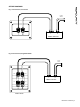
CONNECTION V4 Single Wire Mode: The terminal panels have captive link bars fitted as standard to link the positive and negative HF and LF terminals respectively. These must be removed to Bi-Wire the speakers - see section entitled Connection in Bi-Wire mode. (See fig. 2) For optimum performance in single wire mode, loudspeaker cable connections from the amplifier should be made to the high frequency (HF) terminals of the loudspeaker: Connect as instructed above for V1, VC & VR. (See fig.
POSITIONING AND FINE-TUNING To get best results from your new Tannoy Mercury V loudspeakers it is worthwhile spending a little time finding the optimum set-up configuration. Begin by angling the speakers towards your chosen listening position, usually this is on the centre line of the room, so that when seated you can just see the inner side panel of each speaker. The front of the loudspeaker should not be obstructed in any way. The loudspeakers should be located between 1.5 to 4.
MERCURY V HOME THEATRE 5.1 - GENERAL INFORMATION Unlike other forms of encoded surround audio, 5.1 offers full bandwidth capability for the surround and centre channels, with the ability to treat the subwoofer as a single discreet channel for special effects playback or, for music applications, as a dedicated low frequency instrument channel. This places new demands on the surround and centre channel loudspeakers in both the mixing environment and the playback environment. The 5.
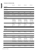
TECHNICAL SPECIFICATIONS Mercury V1 Mercury V4 Mercury VR Mercury VC Recommended amplifier power (Watts RMS) 10 - 70 10 - 140 10 - 60 10 - 90 Continuous power handling (Watts Peak RMS) 50 100 40 70 Peak power handling (Watts) 100 200 80 140 Sensitivity (2.83 Volts @ 1m) 86dB 91dB 86dB 90dB Nominal Impedance (Ohms) 8 8 8 8 Frequency response (-6dB) 45Hz – 25kHz 32Hz – 25kHz 57Hz – 25kHz 67Hz – 25kHz 25mm (1.
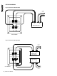
SET-UP DIAGRAMS Fig. 1 Connection V1, VC and VR TO RIGHT SPEAKER + L + R POWER AMPLIFIER Fig.
SET-UP DIAGRAMS Fig. 3 Connection V4 Bi-Wire Mode TO RIGHT SPEAKER HF- HF+ + L - + R POWER AMPLIFIER LF- LF+ LINKS REMOVED Fig.
SET-UP DIAGRAMS Fig. 5 Recommended Positioning - Stero Pair 0.5 METRES OR MORE 1.5 TO 4.5 METRES 1 METRE OR MORE 1.0 METRE OR MORE Fig. 6 Recommended Positioning - Home Cinema CENTRE 0.5 METRES O 1.5 TO 4.5 METRES REAR 0.
T: 00 44 (0) 1236 420199 T: 00 49 (180) 1111 881 T: 00 45 8742 7000 T: 00 1 (519) 745 1158 E: enquiries@tannoy.com E: anfragen@tannoy.com E: info@tcgroup-international.com E: info@tcgroup-americas.com Tannoy adopts a policy of continuous improvement and product specification is subject to change.