
User Manual

Graupner
GmbH & Co. KG * Henriettenstraße 94-96 * D- 73230 Kirchheim/Teck * www.graupner.de
9
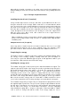
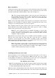
Motor installation
Prepare the area where the motor mount is to be bonded to the inside of the fuselage
nose with a course abrasive paper (80 Grit) to ensure a good bond. The motor mount
should be installed about 1mm behind the edge of the fuselage nose.
Tip: Fit a long nylon bolt through the centre hole in the motor mount and use
the protruding part of the bolt as an aid to adjusting the precise amount of
down-thrust and side-thrust. The bolt also serves as a useful handle while
positioning the motor-mount in place.
With the motor temporally installed, fit the propeller yoke and spinner and check the
alignment of the fuselage nose with the spinner. Carefully finish the front of the
fuselage nose to match the profile of your chosen spinner.
Now carefully position the motor mount in place and secure with a few drops of
instant adhesive before finally bonding in place with a generous bead of suitably
thickened epoxy to both sides of the motor mount.
Note: Be sure to make provision for adequate air-intake to cool the drive
system. Some customers may prefer to use a so called Turbo-Spinner which
provides for intake of air through the spinner itself, but do make sure that
adequate cooling is provided.
Only when the motor-mount is fully secure, re-install the motor (remember to use lock
washers) and ensure that the drive shaft turns feely and there is adequate
clearances for the propeller yoke and spinner assembly. A gap of about 1mm
between the spinner and the fuselage nose is recommended. For the sake of safety,
don’t install the propeller until the model is complete!
Note: Check that the screws used to secure the motor to the motor mount are
not too long as they may otherwise foul the internal motor mechanism. You
may find it necessary to countersink the mounting screws slightly, to achieve
clearance with the propeller yoke/spinner assembly.
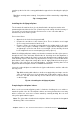
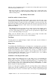
Installing the battery & servo frame
Select the battery & servo mounting frame from the wooden parts set. The front of
the mounting frame is to be located about 140mm from the rear of the cockpit
opening. Make sure that there is sufficient space in front of the servo mounting frame
to accommodate your chosen battery pack and adjust to suit.
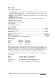
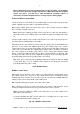
Fig 8. Battery & Servo Frame
Note: The mounting frame does fit in the fuselage opening! Turn it around carefully
and you will find that it will slip neatly into place. Don’t be tempted to sand away
too much material which will result in a poor fit.
Mark the position carefully with a pencil. Now remove the two protective strips from
the inside of the fuselage opening and tack the servo frame in place using an instant