
User Manual

Graupner
GmbH & Co. KG * Henriettenstraße 94-96 * D- 73230 Kirchheim/Teck * www.graupner.de
5
Important Note regarding Styrofoam wing cores.
For all joints involving Styrofoam wing cores it is essential that you do not use
any solvent based adhesives, and in particular avoid use of any form of cyano-
acrylate glue. Use of such adhesives will destroy the foam and render the
affected parts useless. Use only solvent-free adhesives, such as Epoxy resin
and/or Aliphatic Resin (white wood glue) if working anywhere near exposed
areas of Styrofoam.
Notes regarding the use of Epoxy Resin.
Epoxy alone is not a viable adhesive! However, the addition of appropriate additives
makes for a variety of excellent adhesives. Match the choice of additive to the job at
hand:
1. Chopped cotton fibres – produces a tough but flexible joint.
2. Superfine glass fibres - makes a hard joint.
3. Microballoons – produces a highly effective, lightweight filler.
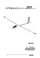
Assembling your ALPINA 2501 ELEKTRO.
The kit you have purchased includes all the parts required to complete the basic
airframe (ARC) and covering (ARF), but does not include adhesives or radio control
components. You can make a significant contribution towards the ultimate
appearance and performance of your model by building carefully and accurately. It is
a well known fact that a poorly built model does not fly well and may be difficult to
control. A well built and properly trimmed model will reward the pilot and spectators
with good performance and accurate handling characteristics. Be patient, take your
time; the effort will be well worth while!
The Fuselage and Empennage.
Begin the construction with the Fuselage as this is the point of reference for all other
parts.
Fuselage Openings / Wing faring.
Open out all of the openings in the fuselage. Use a 2 mm dia. drill to make a series of
small adjacent holes to prepare the openings in the in the area of the wing fairing.
Finish the openings using a small file as indicated by the markings in the mould.
Tip. Use a needle file or suitable rotary tool to finish the job.
Compression Struts
Two compression struts are installed inside the fuselage, between the wing roots at
both leading and trailing edge positions to prevent damage to the fuselage when the
wings swing forward following a heavy landing. The front strut is located in front of
the Multilock connector and the rear strut is located just behind the trailing edge wing
incidence pins. Take care that the struts do not distort the shape of the fuselage.
Check by temporarily installing the wings and adjust the length of the struts to
achieve a snug fit between the fuselage sides. Note that once installed, the front
compression strut will restrict access to the fuselage opening, so you may wish to