
User Manual

Graupner
GmbH & Co. KG * Henriettenstraße 94-96 * D- 73230 Kirchheim/Teck * www.graupner.de
11
the holes in the opposite side of the fuselage using a sharpened 3mm steel rod (or
similar tool).
Remove the wing and drill the holes in the wing root using a 3mm twist drill.
Remember to take account of the wing dihedral; the holes should be drilled parallel to
the wing joiner. Once both wings have been marked and drilled, the four incidence
pins can be bonded into place using a slow setting thickened epoxy. Be sure to make
one pin in each wing a little longer than the other, and round off the end of the pins to
facilitate easier assembly at the flying field.
Note! Apply a suitable release agent (floor wax works well) to the holes in the
fuselage sides and to the fairing itself before applying the adhesive, then fit the
wings to the fuselage, with the steel joiner installed to allow the epoxy to cure
overnight
.
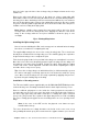
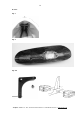
Fig. 9. Floating Wing Joiner
Installing the Nylon wing locks.
Note: Customers building the ARC version may prefer to wait until after the wings
have been covered before completing this step.
The supplied Nylon wing locks are used to secure the wing joints. The sockets have
already been installed in the fuselage wing root. The matching plugs are required to
be glued into the wing roots to complete the joint.
First check the plugs fit the holes provided in the wing roots and adjust if necessary.
Once the holes have been adequately prepared, glue the plugs into the wing roots
and with the steel wing joiner installed, engage the wings firmly with the mating
sockets and ensure correct alignment. Take due care when completing this step to
avoid the effects of any excess epoxy.
Tip. Cover the fuselage wing roots with kitchen film (or similar material) to protect
the surface and apply a releasing agent to the locks themselves while the epoxy
cures. Once cured, the wing locks are easily separated by applying firm pressure,
by hand, along the leading edge of the wing.
Installation of the wing servos.
The TA Servo LOCK system supplied with your ALPINA 2501ELEKTRO kit provides
a universal wing servo mounting mechanism which is both simple and very secure.
Remove sufficient polystyrene to the inside the factory prepared servo-wells to
accommodate your chosen servos up to the inside of the upper wing skin. Reinforce
the area of the upper wing skin with a small piece of 100 g./dm ² glass cloth and
epoxy resin. This prevents stress points in the upper wing skin as a result of installing
the servos. Finally glue the plywood servo mounting frames to servo openings in the
wings.
Note: In the case of the ARF version, the plywood servo frames are pre-
installed at the factory.
The servos themselves are simply bonded to the inside of the servo cover scoop
using suitably thickened epoxy and screwed onto the plywood frames (see also the