
User manual


Tandberg Data
Operation and Configuration
StorageLoader Installation and User Manual
21
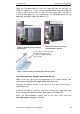
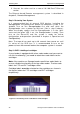
Step 4. Removing the Transport Lock
The robot m echanism
is protected from
damage during
shipment with a
screw holding the
robotics in a locked
position.
This locking screw is
marked with a red
plastic tab protrudin
g
between the right
magazine and the
front panel assembly.
This locking screw
must be removed
before the
StorageLoader can
operate normally.
Figure 3.9
Robotics
lock marked with red plastic tab
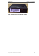
The locking screw will be detected when the StorageLoader
is
powered on. The display will show a message indicating the locking
screw has been detected. The display will instruct the user to
remove the magazine to gain access to the locking screw. Rem ove
the screw and reinsert the magazine. The loader will now co
ntinue
its power on sequence, see next step.
For manual/emergency release of the magazine, see section
4.8.5
.
Note
: Keep the screw in a safe place. You will need it to lock the
robot if you need to return your StorageLoader to the supplier for
service or repair.
Important:
The warranty does not cover damage to the loader,
shipped without the locking screw properly installed. See section
6.4
,
Reinstalling
the
Transport
Lock
, on how to re-install the
transport lock.
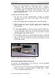
Step 5. Running Power
-
On Selftest
After the transport lock is removed, the loader will continue
running it’s power-on selftest and doing an inventory of its
cartridges.
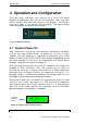
The word Idle and the cartridge map will appear on the default
display screen. If the self-diagnostics and the inventory sequence
are successfully completed, the green LED will illuminate. The
StorageLoader is now ready to be installed in the system.