
User manual


Tandberg Data
Operation and Configuration
StorageLoader Installation and User Manual
13
2.2.2
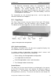
Rear Panel
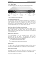
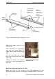
The figure below shows the rear panel of the StorageLoader.
Main
Power
switch
Fuse
Power cord
connection
Fan
Back panel
cover plate
Fan
SCSI
connectors
Ethernet
port
F
igure 2.5 Rear panel of the StorageLoader
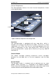
Two Integrated Cooling Fans
The rear panel contains two forced-air cooling fans, which draw air
inward through the front and expel it out in the back. The fans will
start whenever the drive is operating or when the internal
temperature in the StorageLoader gets too high. The cooling fans
are field replaceable units, see section
6.5.4
,
FRU
Fan
.
Main Power Switch/ Fuse/Pow
er cord connection
The main power switch is found on the rear of the loader on the
power supply bracket. The power switch, the fuse holder (with a
250V 2A (H) fuse) and the AC power cord connection are combined
in one common unit.
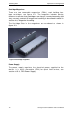
SCSI Interface Connectors
The StorageLoader has two shielded 68-pin VHDCI SCSI
connectors on the rear panel. The connectors are used for
connecting the tape drive and the StorageLoader to a SCSI bus.
These connectors can link to the following:
A shielded male VHDCI SCSI cable
A
shielded male VHDCI SCSI terminator.
Ethernet Port
This port is for the Rem ote Management system and allows you to
connect the StorageLoader to a 10/100 BaseT Ethernet network.
Back Panel Cover Plate
Rem oving the Back Panel Cover Plate gives you access to all the
field
-
replaceable units located at the back of the StorageLoader.