StorageLoaderTM INSTALLATION AND USER MANUAL TANDBERG DATA ASA P.O. Box 134 Kjelsås N-0411 OSLO, NORWAY Phone + 47 22 18 90 90 Telefax + 47 22 18 95 50 www.tandberg.com © Tandberg Data ASA Part No.
Related publications available from Tandberg Data ASA: Part No. Title 432980 Tandberg Data StorageLoader SCSI Interface Functional Specifications. 433060 Tandberg Data StorageLoader Quick Installation Guide This publication may describe designs for which patents are granted or pending. By publishing this information, Tandberg Data ASA conveys no license under any patent or any other rights. Every effort has been made to avoid errors in text and diagrams.
Table of Contents 1. About This Manual...................................................... 5 2. General Information................................................... 7 2.1 2.2 Models .............................................................. 8 2.1.1 Capacity ................................................... 8 2.1.2 Data Transfer Rates.................................... 8 Product Description............................................. 8 2.2.1 Front Panel..........................................
Tandberg Data 5.1 5.2 About This Manual Remote management configuration...................... 48 5.1.1 Quick start guide....................................... 48 5.1.2 Enabling the RMI without rebooting ............. 48 Remote management web pages ......................... 49 5.2.1 Information Boxes..................................... 49 5.2.2 StorageLoader Start Page........................... 50 5.2.3 Status Page.............................................. 51 5.2.4 Settings Pages .................
Tandberg Data Remote Management Table of Figures Figure 2.1 Overview of Tandberg Data StorageLoader 1U ... 7 Table 2- 1 Data Storage Capacity ................................ 8 Table 2- 2 Data Transfer Rates .................................... 8 Figure 2.2 Front panel of the StorageLoader ..................... 9 Figure 2.3 Internal components of the StorageLoader ...... 11 Figure 2.4 Cartridge magazines..................................... 12 Figure 2.5 Rear panel of the StorageLoader ...................
Tandberg Data About This Manual Figure 5.3 Remote Management Status Page .................. 52 Figure 5.4 Remote Management Command Page ............. 54 Figure 6.1 Transport lock marked with red plastic tab ..... 58 Figure 6.2 Field Replaceable Units ................................. 60 Figure 6.3 Replacing the tape drive ............................... 61 Figure 6.4 Rear of the tape drive................................... 61 Figure 6.5 Releasing the tape drive ..............................
Tandberg Data Table Table Table Table Table A- 6 A- 7 A- 8 A- 9 A- 10 Table B- 1 Remote Management StorageLoader drop test ............................ 90 StorageLoader temperature specification ..... 90 StorageLoader humidity specification .......... 91 StorageLoader altitude specification ............ 91 StorageLoader noise specification ............... 91 List of spare parts and accessories .............. 92 1.
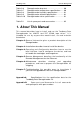
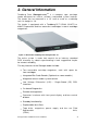
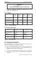
2. General Information Tandberg Dat a StorageLoaderTM is a com pact t ape cart ridge loader designed for secure, reliable, unat t ended syst em backup. The loader can be m ount ed in a 19” rack or used as a t ablet op unit. Its height is 1U. The loader is equipped wit h a Tandberg DLT VS160, 220LTO or 420LTO tape drive and has room for 8 cartridges in two 4- cartridge magazines. Figure 2.
Tandberg Data Operation and Configuration *** IMPORTANT *** Review the READ ME FIRST caution at the beginning of Chapter. 3 before you power up the unit for the first time. Models.For addit ional specificat ion model, refer to Appendix A. inform at ion for t his 2.1.1 Capacity StorageLoader Model Cartridge Capacity (Native) Cartridge Capacity (Comp 2:1) Magazine Capacity (Native) Magazine Capacity (Comp 2:1) Tandberg StorageLoader LTO1 100GB 200GB 800 GB 1.
Tandberg Data Operation and Configuration An Et hernet connect ion allows for m anagem ent by an operat or wit h a st andard web browser on a rem ot e com put er. The rem ot e operat or can do m ost of t he operat ions t hat can be done t hrough t he front panel, such as m onit oring t he loader’s st at us and downloading st at ist ical and diagnostic information. For inform at ion on t he inst alled t ape drive; see t he t ape drive manuals referred to in chapter 1. 2.2.
Tandberg Data Operation and Configuration any activity is always visible on the display. LED Indicators The t wo LED indicat ors are green and am ber. They indicat e t he StorageLoader activity as follows: Green LED on: The St orageLoader is eit her running or ready for operation. Green LED blinking: Short blinks followed by long int ervals indicate that the loader is in low power standby mode. Am ber LED on: Fault LED, t he St orageLoader encountered an electrical or mechanical failure.
Tandberg Data Operation and Configuration Internal Components The St orageLoader feat ures t he m ain int ernal com ponent s shown in the figure below. Drive Slot 4 Slot 3 Slot 2 Slot 1 Power Supply Cartridges Slot 8 Robotics module Slot 7 Slot 6 Left magazine Slot 5 Front panel Right magazine Figure 2.3 Internal components of the StorageLoader Tape Drive The St orageLoader is equipped wit h one t ape drive, which is locat ed in t he cent re in t he back of t he loader.
Tandberg Data Operation and Configuration Cartridge Magazines There are t wo rem ovable m agazines ( FRUs) , each holding four t ape cart ridges, see figure 2.4. The m agazine includes design features to ensure that cartridges are always inserted correctly and stay securely seated. All magazine handling is described in detail in section 4.8, Magazine Handling. The Cart ridge Slot s in t he m agazines are num bered as shown in figure 2.3 Figure 2.
Tandberg Data Operation and Configuration 2.2.2 Rear Panel The figure below shows the rear panel of the StorageLoader. Main Power switch Fuse Power cord connection Fan Back panel cover plate Fan SCSI connectors Ethernet port Figure 2.5 Rear panel of the StorageLoader Two Integrated Cooling Fans The rear panel cont ains t wo forced- air cooling fans, which draw air inward t hrough t he front and expel it out in t he back.
Tandberg Data Operation and Configuration 3. Installation This chapt er provides st ep- by- st ep inst ruct ions on how t o properly prepare and install the Tandberg Data StorageLoader. READ ME FIRST CAUTION! ! YOU MUST REMOVE THE ROBOT TRANSPORT LOCK WHEN POWERING UP THE UNIT FOR THE FIRST TIME OR IT WILL NOT OPERATE. SEE THE PROCEDURE ON THE FOLLOWING PAGES. 3.1 Performing the Installation To install the StorageLoader, complete the following steps. Step 1.
Tandberg Data Operation and Configuration - 2 Line Power Cords: one for USA/ Japan and one for European power outlets - 1 VHDCI SCSI Interface Cable - 1 68- pin VHDCI LVD/SE SCSI Terminator. - 1 Ethernet cable - Tool for Emergency Magazine Release - 30 StorageLoader specific Bar code labels There will be variat ions of t his list . Please also refer t o your Quick I nstallation guide shipped with the StorageLoader. Note: The StorageLoader contains no cartridges before shipment. Step 2.
Tandberg Data Operation and Configuration Folding rule or tape measure Screwdriver 7 mm open- end wrench Note: The rails are m ount ed t o t he loader during t ransport at ion. Before mounting the rails into the rack, dismount the rails from the loader and remove the spacers between the rails and the loader. Back Rail Right Assembly Rail Left Assembly Front Figure 3.1 Rack Mounting kit Installing the Rack Mounting Kit Determine the proper position of the rails in the rack.
Tandberg Data Operation and Configuration St orageLoader 1U uses 1U of vert ical rack space. The rails m ust be inst alled in a full U posit ion ( The bot t om of t he rails m ust be aligned wit h t he bottom of a U), see figure 3.2. Figure 3.2 Rack mount rail Installing the “Rail Left Assembly” 1. Measure t he lengt h bet ween t he rear rack m ount rails and t he front rack m ount rails.
Tandberg Data Operation and Configuration Use these holes if rack depth is equal or longer than the StorageLoader Rear Rack Mount Rail Step 1 Holes to be used if rack depth is shorter than the StorageLoader Step 5 (Screw M6x12) Step 1 Front Rack Mount Rail Step 3 (Screw M4x12, nut and washer) Step 2 Step 5 (Screw M6x12) Figure 3.3 Mounting the Rack mounting kit to a rack Figure 3.
Tandberg Data Operation and Configuration Slide t he St orageLoader on t he rails from t he front of t he rack, as shown in figure 3.5. Then fix t he St orageLoader using one M6x12 screw in front of t he rack on bot h left and right side ( see figure 3.6) and one M5x8 on t he backside of t he Rack Mount ing Kit on both left and right side (see figure 3.7). Figure 3.5 Slide the StorageLoader in from the front Figure 3.
Tandberg Data Operation and Configuration Step 3. Connecting Power Cable The StorageLoader is offered both with AC and DC connection. - DC connection. This version is offered wit h special connect or and - 48 VDC voltage. This is described in appendix. A2. Please not e grounding requirements and special connector. AC connection Before connect ing t he St orageLoader t o your host com put er syst em you should run t he self- diagnost ic of t he unit .
Tandberg Data Operation and Configuration Step 4. Removing the Transport Lock The robot m echanism is prot ect ed from dam age during shipm ent wit h a screw holding t he robot ics in a locked position. This locking screw is m arked wit h a red plast ic t ab prot ruding bet ween t he right m agazine and t he front panel assembly. This locking screw must be removed before the StorageLoader can operate normally. Figure 3.
Tandberg Data Operation and Configuration I f a problem occurs during t he power- on sequence, t he St orageLoader will display an error m essage on t he display. Refer t o chapt er 4.2 and 7, t o learn t he procedures for resolving t he problem. Step 6. Setting the SCSI Address The SCSI address is a unique address t hat ident ifies t he unit connect ed t o t he SCSI bus. The St orageLoader uses t wo SCSI addresses or I d’s.
Tandberg Data Operation and Configuration D) Before t he St orageLoader is powered on and t he syst em is rest art ed, m ake sure t hat t he SCSI bus is properly t erm inat ed. I f t he St orageLoader t erm inat es t he SCSI bus, it is recom m ended t o connect t he t erm inat or from t he accessory kit box on t he lower SCSI connect or on t he back plane. See figure 3.10. To connect the SCSI bus cable: 1.
Tandberg Data Operation and Configuration 2. Connect t he ot her end t o a norm al 10/ 100 BaseT Et hernet outlet. The Et hernet - based Rem ot e m anagem ent syst em is described in chapter 5, Remote Management. Step 9. Restarting Your System I t is recom m ended t hat all ext ernal SCSI devices, including t he StorageLoader are powered on before t he com put er syst em is restarted. Turn on t he StorageLoader first and wait while t he St orageLoader runs a power up Self- t est ( like in st ep 5 above) .
Tandberg Data Operation and Configuration Figure 3.12 Positioning of bar code label for DLT cartridges.
Tandberg Data Operation and Configuration 4. Operation and Configuration The Local User I nt erface ( LUI ) consist s of a sm all LCD panel capable of displaying four lines of 20 charact ers each, and four cont rol but t ons, one near each corner of t he display. The but t ons have soft labels in t he corners of t he display. The figure below shows the power- on screen on the panel. Figure 4.1 Power-on Screen 4.
Tandberg Data Operation and Configuration Default screen, see figure 4.3 appears and t he loader is ready for SCSI commands. The Map of the cartridges has the following symbols: 1. A “?” when status is unknown and Inventory is still running. 2. A num ber indicat es a slot occupied by a cart ridge ( figure 2.3 shows how t he cart ridge slot s are num bered in t he magazines) 3. Underscore line indicates an empty slot 4. ‘C’ indicates that a Cleaning Cartridge occupies the slot.
Tandberg Data Operation and Configuration The Drive Status line (line 3) can show the following status: 1 Drive Empty There is no cartridge in the drive 2 Drive Loaded A Cartridge is Loaded.
Tandberg Data Operation and Configuration 4.2 Front Panel Display Modes The front panel displays t hree t ypes of screens for different purposes: the Menus, the Dialogs and the Messages. 4.2.1 Menus The m aj or cont ribut or is t he MENU. I t is used t o select operat ions t o perform by enabling t he operat or t o navigat e a m enu t ree using the control buttons. Due to the size of the display, only one menu item is shown at a time. See figure 4.4 for a standard menu layout and figure 4.
Tandberg Data Operation and Configuration Figure 4.
Tandberg Data Operation and Configuration 4.2.2 Dialogs A dialog is a screen t ype used t o get det ailed input from t he operat or, for exam ple a SCSI I D, a nam e or a password. See Figure 4.6. ? Ok Main Dialog text Dialog Entry value ? Figure 4.6 Standard Dialog Layout. The dialogs com e in several form s, but t here are only a few m ain types. Dialogs, Discrete Values The dialog in Figure 4.7 is used t o ent er discret e values. I t handles one charact er or digit at a t im e.
Tandberg Data Operation and Configuration Examples: If the value “0” or “1” is selected in the Fixed IP address dialog above, the user is allowed to select values between “0” and “9” as the next two digits. (The maximum value allowed in this dialog is “255” within each group.) If, however, “2” is selected, only values between “0” and ”5” are available in the second digit.
Tandberg Data Operation and Configuration Here, t he user can scroll t hrough a set of opt ions one at a t im e by using t he left and right arrow but t ons. Only one opt ion is shown at a t im e. I n t he exam ple above, t he user can select eit her “ Enabled” or “Disabled” mode. This kind of menu also has a Cancel function. 4.2.
Tandberg Data Operation and Configuration 4.3 Main Menu The Main m enu cont ains a set of frequent ly used funct ions and links to a set of sub menus. Item name Description Load to Drive Loads a cartridge from a selected magazine slot into the drive. When Select is pressed on this menu item, a magazine slot selection dialog is displayed. The operator has to scroll to the wanted slot and press Ok to start the operation.
Tandberg Data Utilities Operation and Configuration Selects a set of the loader and drive maintenance and diagnostic functions. The loader must be idle to make this entry selectable. See chapter Utilities Menu for more details. The Main m enu can be select ed even if t he loader is not in t he idle st at e. While in t he m ain m enu, t he loader will accept and execut e SCSI com m ands.
Tandberg Data Operation and Configuration 4.4.2 SCSI Setup The SCSI set up m enu allows select ion of SCSI addresses for bot h t he Loader and it s int ernal drive. I n addit ion, t he SCSI bus Parit y can be enabled or disabled. Because of t he SCSI prot ocol, t he values select ed will only t ake effect aft er t he next Reset of t he Loader and Drive. Item name Legal values. Default value Loader SCSI ID Legal SCSI ID: 00..15 04 Drive SCSI ID Legal SCSI ID: 00..
Tandberg Data Operation and Configuration * Used only while the IP address assignment is in Static mode. 4.4.3.1. Remote Management Access Control Item name Legal values. Default value Allow Remote Management Allowed, Not allowed Allowed Allow Remote FW download Allowed, Not allowed Not allowed 4.5 View Data Menu To ent er t his m enu, scroll t o t he View Dat a it em in t he m ain m enu and press t he Select but t on. The loader will rem ain in it s ready state when this menu is selected.
Tandberg Data Operation and Configuration Cleaning Slot Defined cleaning slot, Disabled Disabled Barcode Reader * Enabled, Disabled Enabled if installed, else Disabled Loader Serial No. Loader Serial number. --- Loader FW revision StorageLoader FW id and revision xx.
Tandberg Data Operation and Configuration 4.5.3 Remote Management Info The Rem ot e Managem ent ( RMM) set up is shown in t he choices list ed below. This m enu t hree is t he place t o find t he current ly allocat ed dynam ic I P address, default gat eway and net work m ask when running in DHCP m ode. The MAC address of t he Loader is also shown here. Item name Legal values Default value IP address mode Static mode, DHCP mode DHCP mode Static IP address 0.0.0.0 to 255.255.255.255 0.0.0.
Tandberg Data Operation and Configuration Diagnostics Displays a list of exercise test programs Access control Set Password 4.6.1 The Maintenance Menus Item name Description Prepare to Ship When selected the robotics will be positioned for installation of the locking screw. It will eject the Right magazine to facilitate the installation. It will also eject the left magazine if it contains one or more cartridges.
Tandberg Data Operation and Configuration 4.6.3 Set Password Item name Description Set Password Allows the operator to set a four- digit password protection for the menu system. The default password is <0000>, meaning the password is disabled. WARNING: If you set a password, make sure you do not forget it. If you do, it ca n on ly be cle a r e d w it h a ssist a n ce fr om Ta n dbe r g D a t a t e ch n ica l support or by a qualified service technician. 4.7 Cartridge Handling 4.7.
Tandberg Data Operation and Configuration 3. Press the Ok button. The robot rem oves t he cart ridge from t he select ed m agazine slot and moves it to the drive. To unload a cartridge from drive: 1. From t he default display, press t he m enu but t on and select Unload from Drive from t he m ain m enu. A screen pict ure like figure 4.12 will be displaying the available slots. Ok Cancel Unload from drive To Slot: 24678 Figure 4.12 Load to Drive 2. Select t he cart ridge slot num ber of your choice.
Tandberg Data Operation and Configuration Note: You cannot rem ove t he m agazine if t he unit is password prot ect ed or locked by host soft ware t hrough a Pr e ve nt M e dium Removal SCSI command. Before you can rem ove a m agazine, t he loader m ust be idle. When t he loader is idle, press t he Menu but t on and select t he Ej ect Magazine option from the Main Menu. The following magazine: screen, figure 4.14, ? appears, ident ifying t he Exit Eject both mags. ? Select Figure 4.
Tandberg Data Operation and Configuration hand under t he m agazine t o prevent t he back of t he m agazine t o fall down when it leaves the magazine bay. See illustration below. Figure 4.16 Removing the magazine from the loader 4.8.2 Inserting Cartridges into the Magazine When insert ing cart ridges t he access door of t he cart ridge m ust face the magazine. Push it carefully into the magazine until it locks in place.
Tandberg Data Operation and Configuration cart ridge is released. The cart ridge is spring loaded so it is im port ant t o prevent t he cart ridge from popping all t he way out . If t he cart ridge falls down, it m ay be dam aged and dat a m ay be lost. Pull the cartridge carefully out of the magazine slot. Figure 4.18 Push the release knob towards the cartridge to eject Figure 4.19 Cartridge position after manual release from magazine slot 4.8.
Tandberg Data Operation and Configuration 4.8.5 Manual/Emergency Release of Magazines I n case of failure sit uat ions eit her in t he loader it self, a power loss, or if you want t o m anually release t he m agazines for som e ot her reason, a m anual/ em ergency release is available. To act ivat e t he em ergency m agazine feat ure, you m ust use t he special m agazine release t ool which is part of t he accessory kit shipped t oget her wit h t he St orageLoader.
Tandberg Data Operation and Configuration 1. Finish possible StorageLoader activity. 2. Cont rolled abort ing of t ape drive act ivit y; buffered dat a is flushed t o t ape; cart ridge is unloaded from drive but not ejected. 3. The display is turned off. 4. No St orageLoader act ivit y is allowed unt il st andby but t on is pressed again. 5. While in st andby m ode, t he at t ached server/ host can see t he t wo SCSI devices in t he St orageLoader, but t he SCSI st at us will be “not ready.” 6.
5. Remote Management I n order t o facilit at e Rem ot e Managem ent , t he St orageLoader is equipped wit h an Et hernet int erface and a built in web server. The Rem ot e Managem ent I nt erface ( RMI ) can be accessed wit h a standard web browser, such as Internet Explorer, Mozilla or Opera. 5.1 Remote management configuration To be able t o st art t he St orageLoader Rem ot e Managem ent I nt erface, t he St orageLoader m ust obt ain a valid I P address.
Tandberg Data Maintenance 2.1. I f you want t o use a st at ic I P address, use t he front panel t o ent er a valid st at ic I P configurat ion, see sect ion 4.4.3, Remote Management setup. 2.2. I f you want t o configure t he net work subsyst em dynam ically, from t he front panel set Set up Rem ot e management setup IP address mode to DHCP mode. 3. Via t he front panel, first set Set up Rem ot e m anagem ent setup Access cont rol Allow rem ot e m anagem ent t o Not allowed and select OK.
Tandberg Data Maintenance Drive inform at ion cont aining firmware version and activity. t echnology, serial num ber, 5.2.2 StorageLoader Start Page Aft er successfully connect ing t o t he St orageLoader from your browser, you will see t he St orageLoader St art page, figure 5.2. This contains: Select language for user- interface. 1. The language used last t im e will com e up as t he default language at start- up. 2. The default language is English. Log in for furt her use of Rem ot e Managem ent .
Tandberg Data Maintenance Figure 5.2 Remote Management Start Page Note: St orageLoader net work t raffic is not encrypt ed, so anyone wit h physical access t o t he net work pat h will be able t o access t he inform at ion wit h a packet sniffer. Passwords, however, are encrypt ed. I t is not possible t o reach t he plaint ext password, but it is possible t o sniff “ t he challenge key” and use it t o gain access. The system is therefore not safer than the network it is using.
Tandberg Data Maintenance Figure 5.3 Remote Management Status Page The figure provides an updat ed st at us of drives, robot ics and cartridges using color- coding and symbols. The Drive and Robot st at us will be shown as a green ( OK) , yellow ( Warning) or red ( Error) dot . I f you click on t he t ext , addit ional information will be shown in a pop up window. The cart ridge locat ions are shown wit h rect angles in t he slot s or the drive.
Tandberg Data Maintenance I f you click on a slot , addit ional cart ridge inform at ion will be shown in a pop up window. This inform at ion includes t he cart ridge barcode ( if label and barcode reader is inst alled) and t he error code. 5.2.4 Settings Pages On t he set t ing pages, you can change t he St orageLoader configurat ion. These pages can only be accessed by som eone who is logged in as Administrator. Personalization On t his page you can change t he Rem ot e Managem ent passwords.
Tandberg Data Maintenance 5.2.5 Command Page On t his page it is possible t o m ove cart ridges bet ween m agazine slot s and drive. All cart ridges in t he St orageLoader will be found in a pull- down list sort ed by locat ion. The ot her pull- down list shows the empty locations where it is possible to move the cartridge to. Figure 5.4 Remote Management Command Page 5.2.
Tandberg Data Maintenance Debugging Mem ory dum p will download a snapshot of t he syst em m em ory of t he loader t o a file t hat can be sent t o Tandberg Data’s service for diagnostic purposes. Perform a system reset. Media log displays a log of all cart ridge m ovem ent s and a map of the current cartridge locations. 6. Maintenance 6.1 Using the Cleaning Cartridge The cleaning cart ridge is sim ilar in size and shape t o t he regular DLT/ LTO dat a cart ridge.
Tandberg Data Maintenance c. a cartridge in the slot defined as the cleaning slot. If all of the above fails, the loader will display a dialog asking the operator for the slot to fetch the cleaning cartridge from. 3. While the cleaning operation is on- going, the display shows the drive status “Drive Cleaning”. When the operation is completed the cartridge is automatically moved back to the slot where it was fetched from.
Tandberg Data Maintenance 6.2 Installing Firmware Upgrades The loader FW can be upgraded via the SCSI interface. 6.2.1 Firmware Upgrade via SCSI A suit able ut ilit y program , FlashI t , and t he lat est FW im age file, can be downloaded from t he Tandberg Dat a web sit e http://www.tandberg.com/. The program is available for Win XP, Win 2000/2003, Win Nt. Note: Read this entire procedure before you perform an upgrade. 1.
Tandberg Data Maintenance flashes in addit ion t o t he Am ber LED being lit . The program m ing operat ion takes less than one minute. 9. When reprogram m ing is com plet ed, t he loader will do a normal reboot I f t he firm ware upgrade operat ion failes during point 8 due t o a power shut- down or similar, the loader may require service. To verify t hat t he FW version in t he loader is correct , ent er t he view dat a m enu.
Tandberg Data Maintenance installed. The t ransport lock m ust be rem oved prior to operation. 6.4.1 Transport Lock Installation Procedure To insert the locking screw do the following: 1. If there is a cartridge in the drive, unload the drive first. When the loader is powered on and idle, push the M enu button and go to the Prepare to Ship menu entry (see section 0, 2. The Maintenance Menus). 3.
Tandberg Data Maintenance Figure 6.2 Field Replaceable Units 6.5.
Tandberg Data Maintenance For replacing the tape-drive, switch off the loader, disconnect the power cord and remove these two screws and the back-panel cover plate. Figure 6.3 Replacing the tape drive You now have access to the rear of the tape-drive and can dismount the SCSI cable, the ADI cable and the power cable. SCSI cable ADI Cable Power connector Figure 6.4 Rear of the tape drive Release the tape-drive by pushing the spring against the gripper-plate and pulling the drive carefully backwards.
Tandberg Data Maintenance After removing the defective drive, the drive mounting brackets on both sides of the drive must be removed from the drive, since these will be used for mounting the replacement- drive. The drive mounting brackets are fastened with two screws each. The replacement drive comes with a front bezel which is snapped onto the front of the drive. Remove the front bezel and keep it for use when returning the defective drive.
Tandberg Data Maintenance Snap the front bezel that was removed from the replacementdrive onto the front of the defective drive. Then pack the defective drive in the same box you received the replacementdrive and return it to your support center. 6.5.
Tandberg Data Maintenance You now have access to the rear of the tape-drive and can dismount the SCSI cable, the ADI cable and the power cable. Power cable ADI cable SCSI cable Figure 6.9 Rear of the tape drive Release the tape-drive by pushing the spring (see arrow) against the gripper-plate and pulling the drive carefully backwards. Figure 6.
Tandberg Data Maintenance drive and the brackets laying on a level surface to ensure the brackets are aligned with the bottom of the drive. Fasten the brackets with two screws each. Insert the replacement drive carefully into the loader the same way it was removed, reconnect the 3 cables (the ADI cable is mounted closest towards the SCSI cable) and re- mount the back plate. Snap t he front bezel t hat was rem oved from t he replacement- drive ont o t he front of t he defect ive drive.
Tandberg Data Maintenance supply and carefully unhook t he connect ors for power and fan ( Figure 6.13) before com plet ely rem oving t he power- supply module. Fan power cable Power connector Figure 6.13 Fan power Aft er rem oving t he power- supply, insert t he replacem ent unit carefully t he sam e way, reconnect t he 2 cables, fast en t he fixing screw and re- m ount t he back plat e.
Tandberg Data Maintenance Figure 6.15 Removing the fan Rem ove t he fan fixing screws ( Figure 6.15) . Unhook t he power connect or of t he fan and carefully replace it . When re- insert ing t he fan t ake care t o have t he cable in t he not ch in t he chassis. I f t he cable is not fully inside t he not ch it can easily be dam aged and cause a new faulty fan. Fasten the fan fixing screws. Fan power cable Cable notch in chassis Figure 6.
Tandberg Data Maintenance 6.5.5 FRU Magazine The FRU Magazine for t he LTO version consist s of t he following parts: LTO Magazine FRU StorageLoader 1U Ite Part no Description m 1 S80873 Magazine Left LTO 8 2 S80873 9 Magazine Right LTO Qty 1 1 The FRU Magazine for t he DLT version consist s of t he following parts: DLT Magazine FRU StorageLoader 1U Ite Part no Description m 1 S80873 Magazine Left DLT 1 2 S80873 2 Magazine Right DLT Qty 1 1 See section 4.8, Magazine Handling for instructions.
Tandberg Data Maintenance 6.5.6 FRU Filter This FRU consists of the following parts: S808741 Filter FRU StorageLoader 1U Item Description 1 Filter 2 Quick Installation Guide Filter Qty 1 1 When needed, t he dust filt er can be pulled out and a new one slid int o t he front - bezel assem bly of t he m agazines. We recom m end t o replace t he dust filt ers once every year. Figure 6.
Tandberg Data Maintenance 7. Troubleshooting 7.1 How to Take Memory Dumps of the Loader 1. Log in to the remote management interface as Administrator. 2. Navigate to Maintenance Debugging. 3. Click “Memory dump”. 4. Select “Save to disk” in the file download dialog box. 5. Use a zip utility to compress the downloaded memory image. 6. Send the zipped memory image as an email attachment to technical support. Not e t hat t he m em ory im age cont ains t he passwords for t he StorageLoader.
Tandberg Data Maintenance on ot her devices at t ached t o t he sam e SCSI bus and t heir SCSI I Ds, you m ay need t o change t he SCSI I D of t he t ape drive or autolaoder before you can use the autoloader. 2. Verify t hat t he syst em recognizes t he t ape drive and t he loader during the boot process. 3. Verify t hat t he SCSI host adapt er recognizes t he t ape drive and the loader during its initialization. 4. Verify t hat t he st aus on t he loader’s front panel int erface is OK. 5.
Tandberg Data Maintenance I f t he aut oloader has been inst alled previously and operat ing correctly but is now incurring a problem, verify any recent changes to t he syst em t o ensure t hat t hese changes are not causing t he problem. Try the following: 1. I f t he syst em configurat ion has changed: Rem ove t he change to see if it affected the loader. 2. I f an operat ing syst em correct ive pat ch has been inst alled: Remove it to see if it affected the loader. 3.
Tandberg Data The front panel does not display information but the back light on the front panel is on Cartridge movement Loader does not take inventory 74 Maintenance • Power cycle the loader by turning off and on the main power switch on the rear of the loader. • Verify that the fans starts at power on and then stops after a few seconds. • Contact your service representative. • Make sure the transport screw is removed. • Make sure both magazines are in their locked position.
Tandberg Data Cartridge stucked in drive Cartridge stucked in magazine Cartridge stucked in robotics Failed to move cartridges Failed to insert cartridge into drive Media Media barcode labels Maintenance • Power cycle the loader by turning off and on the main power switch on the rear of the loader. Allow both the loader and the drive to complete initialization, which in rare cases can take as long as 10 minutes, and then retry unloading the tape using the autoloader operator panel controls.
Tandberg Data Data cartridge incompatible with drive Cannot write to or read from tape SCSI problems Changed drive or loader SCSI ID, but the host server system does not recognize the new ID The tape drive responds on the SCSI bus to the host, but the loader does not respond 76 Maintenance • Make sure you are using a data cartridges that is compatible with the drive. See the tape drive’s reference manuals for details.
Tandberg Data StorageLoader Installation and User Manual Maintenance 77
Tandberg Data The tape loader responds on the SCSI bus to the host, but the tape drive does not respond Autoloader Performance The autoloader is not efficiently backing up data Cleaning Cannot load the cleaning Cartridge 78 Maintenance • Verify that a SCSI terminator is attached to both the last and first SCSI device on the SCSI bus. • Verify that the SCSI cables are connected to the rear of the loader. See chapter “Installation”, section “connecting the SCSI bus cable”.
Tandberg Data Write or read issues Contaminated head Non-acclimated media Cleaning cartridge is Incompatible Expired cleaning cartridge Bad/defective/contaminated media LED error messages Amber LED on Errors Displayed on Front Panel There is an error code on the LCD display There is an error code on the RMI Remote Management The unit does not respond on the RMI Forgot password Forgot password on RMI Maintenance Avoid contamination by ensuring that the autoloader is installed in a clean, contaminat
Tandberg Data Maintenance Forgot password on FPI • Look up the RMI IP address from the front panel menu (view data menu). • Connect the RMI interface and perform a memory dump of the loader (see user and installation guide for details). • Send the memdump to your Service representative. The FPI password can be decoded from the memdump by using a special SW. 7.
Tandberg Data Maintenance Figure 7.2 Example of detailed information If the problem persists please call technical support. Back Figure 7.3 Example of further detailed information In this example, pressing “Back” twice takes you back to the Error Code Page (figure 7.1) where you can press “Actions” to go to the Actions menu. Figure 7.4 shows an example of pressing “Actions”. Pressing the buttons next to the up/down arrows on the screen gives you access to other action options.
Tandberg Data Maintenance 7.8 Error Codes The error codes are listed in numerical sequence by their Fault Symptom Code (FSC) in the tables that follow. If a persistent error condition prompts you to call your Technical Support representative, be sure to supply the code information to help identify the problem. Error Code Display Message Description 01ZZ Diagnostic number ZZ failed. The diagnostics number ZZ failed. Reboot the loader and retry the operation.
Tandberg Data Maintenance 1209 Failed to fetch at slot 09 Failed to eject cartridge from drive 1. Reboot the loader and retry the operation. 2. Try to eject the cartridge from the drive via the front panel menu. 3.Remove the drive FRU. Connect power to drive and push the drive’s eject button. If this fails, remove cartidge by following the drive’s emergency eject procedure. Defect drive or robotics. Defect cartridge. 2000 Drive not found Communication error between the loader and the drive. 1.
Appendix A – Specifications A.1 Mechanical Dimensions and Weight The Tandberg Dat a St orageLoader 1U is designed as a rack m ount unit. The StorageLoader can also be used as a tabletop unit. Dimensions: Length 740 mm (29.13 in) 0.5 mm from front rail to rear of unit Width 446.6 mm (17.58 in) 0.5 mm Height 43.6 (1.72 in) 0.5 mm Weight 14.6 kg (32.
Tandberg Data Spares/Accessories A.2 Power Requirements Normal AC version. Input voltage 90 VAC – 264VAC Input Frequency 47 Hz – 63 Hz Inrush Current (Cold Start) Less than 30 A, 115VAC Less than 60 A, 230 VAC Power consumption average 35W Power consumption peak* 70W* * Maximum peak length, less than 10ms Table A - 2 StorageLoader Power Requirements Special DC version. Power Ratings - 48 VDC +/- 20 % 1.
Tandberg Data Maintenance Notification. Ref.
Tandberg Data Spares/Accessories Special DC connector: 88 StorageLoader Installation and User Manual
Tandberg Data Maintenance A.3 Vibration Specifications Sinusoidal sweep Sweep Rates Axes Duration Operating 1 octave/minute X, Y and Z 2 hours Frequency Range (Hz) 5 24.2 Non- Operating (Storage) Transport Table A - 3 24.2 5 500 27.1 27.1 5 500 200 Level 0.01 in pp 0.3g 0.02 in pp 0.75g 0.5g StorageLoader sine sweep levels Random Crest factor Axes Duration Operating Total Non Operating/Storage Total Transport Total level Table A - 4 3 X, Y, Z 30 min/axis Frequency (Hz) 5 17 150 200 500 0.
Tandberg Data Spares/Accessories A.4 Mechanical Shock Specifications Mechanical Bump/Shock Axes Directions Pulse interval X, Y, Z Positive and negative 3 seconds Operating Storage (X,Z) Storage (Y) Table A - 5 Pulse shape Half sine Half sine Pulse duration 5ms 8ms Pulse Level 3g 20g Pulses/axis/direction Half sine 8ms 15g 3 1000 3 StorageLoader mechanical shock levels A.
Tandberg Data Table A - 8 Maintenance StorageLoader humidity specification Altitude Operating Non- Operating Table A - 9 Range Range - 500 to 10000 ft - 500 to 40000 ft StorageLoader altitude specification A.7 Noise Specification Acoustic Idle (Lw A) Operating (Lw A) 60 dBA 65 dBA Table A - 10 StorageLoader noise specification A.8 Product Reliability MTBF: 250.000 hours for StorageLoader electronics MSBF: 500.
Tandberg Data Spares/Accessories Type Accessories Table B - 1 92 Description Accessory kit DLT Accessory kit LTO Quick Installation Guide P/N 800246 870157 433060 List of spare parts and accessories StorageLoader Installation and User Manual