Installation and Administration Guide Tandberg Data™ DPS Expansion Module April 2009
Contents Preface . . . . . . . . . . . . . . . . . . . . . . . . . . . . . . . . . . . . . . . . . . . . . . . . . . . . . . . . . . . . . . . . . . . . . . .v About this guide . . . . . . . . . . . . . . . . . . . . . . . . . . . . . . . . . . . . . . . . . . . . . . . . . . . . . . . . . . . . . . v Audience . . . . . . . . . . . . . . . . . . . . . . . . . . . . . . . . . . . . . . . . . . . . . . . . . . . . . . . . . . . . . . . . . . . . v Typographical conventions . . . . . . . . . . . . . . . . . .
Designating hot spares . . . . . . . . . . . . . . . . . . . . . . . . . . . . . . . . . . . . . . . . . . . . . . . . . . . . . . . 33 Backing up the configuration . . . . . . . . . . . . . . . . . . . . . . . . . . . . . . . . . . . . . . . . . . . . . . . . . . 33 5 Troubleshooting . . . . . . . . . . . . . . . . . . . . . . . . . . . . . . . . . . . . . . . . . . . . . . . . . . . . . . . . . . . . . .35 A Upgrading DPS Expansion Module . . . . . . . . . . . . . . . . . . . . . . . . . . . . . . . .
Preface Welcome to the DPS Expansion Module Installation and Administration Guide. Tandberg Data DPS Expansion Module is an external storage array that provides additional storage for Tandberg Data DPS1000 Series™. This guide enables you to install and configure DPS Expansion Module. About this guide The DPS Expansion Module Installation and Administration Guide is designed to help you unpack, rack-mount, cable, power, and configure DPS Expansion Module.
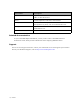
Convention Description Bold Italic Represents variables within file names, command syntax, URLs, or other literal text. Italics Used for emphasis, book titles, and variables. Monospace Used for text that is displayed on-screen, command names and arguments (syntax), code, and command-line text. Monospace Italic Represents variables within command syntax, code, or command-line text. Blue Text Used for cross-references.
Overview DPS Expansion Module provides external storage to increase the amount of storage space for virtual tapes. DPS Expansion Module is compatible with DPS1000 Series. DPS Expansion Module arrays are installed in enclosures. One DPS Expansion Module controller and up to four DPS Expansion Module expansion modules can be cabled together. Controllers have RAID controllers, while expansion modules have disk I/O modules. Each enclosure holds up to two arrays.
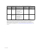
The following DPS Expansion Module models are compatible with DPS1000 Series: Model Enclosure Type Connections Storage Per Array Physical Disk Capacity XDC1200a SAS Controller • SAS connection to DPS1000 Series • SAS connection to other DPS Expansion Module enclosures 3.75TB* 4.5TB XDS1200a-1 SAS Expansion • SAS connection to DPS1000 Series • SAS connection to other DPS Expansion Module enclosures 3.75TB* 4.5TB * Available space for data storage is 6.
Unpacking and Cabling DPS Expansion Module This section provides instructions for unpacking DPS Expansion Module, placing it in a rack, and cabling it to DPS1000 Series, the network, and a power source. Note If you are currently using DPS Expansion Module as external storage and you are upgrading DPS1000 Series, you must also upgrade the DPS Expansion Module firmware. See Upgrading DPS Expansion Module on page 41 for more information.
• • Two (2) ATX rack bracket assemblies universal • One (1) 10 mm spanner (tapped hole rack) Anti-tamper lock tool Additional items needed for installation Gather the following items before you begin installing and configuring DPS Expansion Module: • Terminal or computer running a terminal emulation program • Ethernet cable for controller enclosure • SAS patch cable for each expansion module (in addition to the SAS patch cable shipped with the enclosure) Preparing DPS Expansion Module for mounti
Removing the power supply modules Remove each power supply module as follows: 1. Push the latch above the power supply handle to the right. 2. Grip the handle and pull the module out of the enclosure. WARNING Do not remove the covers from the power supply. There is a danger of electric shock inside. Removing the cooling fan module Remove the cooling fan module as follows: 1. Grasp the latch between your thumb and forefinger. Squeeze your thumb and forefinger together to release the latch. 2.
3. Withdraw the cooling fan module completely from the enclosure. Removing the RAID controller module This section applies to the DPS Expansion Module controller enclosure only. The XDC1200a model used with DPS1000 Series has one RAID controller module. Note The graphics in this section show two RAID controller modules, although the XDC1200a model has only one. Remove the RAID controller module as follows: 1. Using two hands, grasp each latch between your thumb and forefinger of each hand.
3. Grip the latches as handles and withdraw the RAID controller module. Removing the disk I/O module This section applies to the DPS Expansion Module expansion enclosures only. The XDS1200a1 model used with DPS1000 Series has one disk I/O module. Note The graphics in this section show two disk I/O modules, although the XDS1200a-1 model has only one. Remove the disk I/O module as follows: 1. Using two hands, grasp each latch between your thumb and forefinger of each hand.
3. Grip the latches as handles and withdraw the module. Removing drive carrier modules Remove drive carrier modules as follows: 1. If the anti-tamper lock is engaged, carefully insert the lock key provided into the cutout in the handle and into its socket. 2. Rotate the key in a counter-clockwise direction until the red indicator is not visible in the aperture beside the key.
3. To release the drive carrier handle, press the latch in the handle with your finger and rotate the handle towards the right. CAUTION Damage can occur to a drive if it is removed while still spinning. You should perform all steps of the following procedure to ensure that the drive has stopped prior to removal. 4. Gently withdraw the drive carrier module approximately 25 mm (1 inch) and wait 30 seconds for the drive to spin down. 5. Continue to withdraw the module from the drive slot.
Mounting DPS Expansion Module in a rack You must mount the DPS Expansion Module enclosure in a rack. Each DPS Expansion Module enclosure requires 2U of rack space. If you have a DPS Expansion Module controller enclosure and one or more DPS Expansion Module expansion enclosures, be sure to mount the controller enclosure in the rack above the expansion enclosures for easier cabling. To mount DPS Expansion Module 1. Place the empty enclosure chassis on a stable work surface. 2.
d. Tighten the two clamping screws located along the inside of the rear section of the rack bracket. 5. Mount the enclosure in the rack as follows: a. Using an assistant, lift the enclosure aligning it with the rack rails and carefully insert the chassis slides into the rack rails. b. Push the enclosure completely into the rack cabinet. c. Tighten the rear rack bracket mounting screws. (They were previously left loose.) d. Withdraw the enclosure until it reaches the hard stops (approximately 400 mm / 15.
e. Tighten the front rack bracket mounting screws. (They were previously left loose.) f. Push the enclosure completely into the rack cabinet and attach to the front of the rack using the captive fasteners on the front flanges located just outside of the handles.
Installing DPS Expansion Module modules Before you mounted the DPS Expansion Module enclosure in a rack, you removed the DPS Expansion Module modules. You must now reinstall them. Installing the power supply modules Install both power supply modules as follows: 1. Check for damage, especially to the rear connector on the power supply. CAUTION Handle the module carefully and avoid damaging the connector pins. Do not install the module if any pins appear to be bent. 2. Slide the module into the enclosure.
Installing the cooling fan module Install the cooling fan module as follows: 1. Check for damage, especially to the rear connector on the module. CAUTION Handle the module carefully and avoid damaging the connector pins. Do not install the module if any pins appear to be bent. 2. With the latch in the open position, slide the module into the enclosure until the latch engages. 3. Secure the module by manually closing the latch. You will hear a click as the latch engages.
Installing the RAID controller modules The XDC1200a model used with DPS1000 Series has one RAID controller module. Install the RAID controller module as follows: 1. Check for damage, especially to the interface connector. CAUTION Handle the module carefully and avoid damaging the connector pins. Do not install the module if any pins appear to be bent. 2.
3. Secure the module by manually closing the latches. You will hear a click as the latches engage. For the XDC1200a model used with DPS1000 Series, install a blank module in the upper bay.
Installing the disk I/O modules The XDS1200a-1 model used with DPS1000 Series has one disk I/O module. Install the disk I/O module as follows: 1. Check for damage, especially to the interface connector. CAUTION Handle the module carefully and avoid damaging the connector pins. Do not install the module if any pins appear to be bent. 2. With the latches in the open position, slide the disk I/O module into the lower bay located on the right hand side of the enclosure until the latches engage.
3. Secure the module by manually closing the latches. You will hear a click as the latches engage. For the XDS1200a-1 model used with DPS1000 Series, install a blank module in the upper bay. Installing drive carrier modules You must install the disk drives in the same order as they were shipped. All drive slots must be populated with drive carrier modules or dummy carrier modules to maintain a balanced air flow. Install each drive carrier module as follows: 1.
3. Gently slide the drive carrier module all the way into the enclosure until it stops. Seat it by pressing with your thumb on the left edge of the module. 4. Secure the drive carrier module by closing the handle until it fully engages. You will hear a click as the latch engages and holds the handle closed.
5. Engage the anti-tamper locks as follows: Note The anti-tamper locks are fitted in the drive carrier handles and are accessed through the small cutout in the latch section of the handle. Drives are supplied with the locks set in the locked position. a. Carefully insert the lock key provided into the cutout in the handle and into its socket. b. Rotate the key in a clockwise direction until the red indicator is visible in the aperture beside the key. c. Remove the key.
Cabling DPS Expansion Module models XDC1200a and XDS1200a-1 The XDC1200a and XDS1200a-1 models are used with DPS1000 Series. You must connect the controller enclosure to DPS1000 Series, cable together multiple DPS Expansion Module enclosures, connect the DPS Expansion Module controller enclosure to the network, and connect power cords to the enclosures. The following graphics show the back of the controller and expansion enclosures. Use these graphics as you cable DPS Expansion Module.
Connecting DPS Expansion Module to DPS1000 Series and expansion enclosures Use the following graphic as you connect the DPS Expansion Module controller enclosure to DPS1000 Series and to DPS Expansion Module expansion enclosures: Cable type Plug one end into Plug other end into SAS patch SAS port on DPS1000 Series “IN” SAS port on DPS Expansion Module controller enclosure SAS patch “OUT” SAS port on DPS Expansion Module controller enclosure “IN” SAS port on DPS Expansion Module expansion enclosure
Enabling access to the serial command line interface For a DPS1000 Series installation, see Back of XDC1200a controller enclosure on page 21. Cable type Plug the USB end into Plug the RS232 end into RS232 seriala Serial port on DPS Expansion Module controller enclosure Terminal or computer running a terminal emulation program a. This cable has a USB connector at one end and an RS232 connector at the other.
2. Attach the power cord to the power distribution unit in the rack or other power source. (Although the back of each model is different, the power supply modules are in the same location for all models.) WARNING Before applying power, carry out the grounding checks detailed in the following procedure. CAUTION The power connections must always be disconnected prior to removal of the power supply module from the enclosure.
Configuring DPS Expansion Module You can access the DPS Expansion Module web interface and configure email notifications to send alerts to you when DPS Expansion Module events occur. The web interface also shows the current DPS Expansion Module status. Accessing the serial console You may need to access the serial console to set the IP address. The following instructions demonstrate how to access DPS Expansion Module from Microsoft Windows using the HyperTerminal connection wizard.
to an IP address of 10.1.1.5 with a Subnet Mask of 255.0.0.0. If this occurs, check your network configuration (cables, switches, and so on) to ensure they are connected correctly. If this does not resolve the issue, set DPS Expansion Module to use a static IP address. Setting a dynamic IP address Because DPS Expansion Module defaults to DHCP, you do not have to switch to DHCP unless the system defaults to an IP address of 10.1.1.5 or if you are switching from a static IP address to a dynamic one.
Determining the DPS Expansion Module IP address You must know the DPS Expansion Module IP address to access the web interface. To determine the DPS Expansion Module IP address 1. Access DPS Expansion Module through the serial console you connected. 2. Press Ctrl+e to open the console menu. 3. Enter 2 (Diagnostics). 4. Enter 6 (StorView Embedded Module Support). 5. Enter 2 (Enter StorView Embedded Module Menu Mode (Exit with CTRL-W)). 6. Enter 1 (View Network Settings). The console displays the IP address.
To set up email notices 1. On the main page of the DPS Expansion Module web interface, click Settings. 2. In the Settings window, click the Email tab. 3. In the Email Server field, enter the hostname name or IP address of your SMTP email server. 4. To append a signature to messages, select Put Signature into each message and enter text in the field provided. 5. In the Email Addresses area, enter up to 10 email addresses as follows: a. Type the full email address. b.
Installing and Configuring Additional Enclosures Arrays are preconfigured on the DPS Expansion Module controller enclosure and any DPS Expansion Module expansion enclosures shipped with it. You must install and configure any drives and enclosures shipped separately. For every six drives, you can create an array or a set of hot spares. You can attach up to four DPS Expansion Module expansion enclosures with up to two arrays each to an DPS Expansion Module controller enclosure.
4. Power on DPS1000 Series. 5. Power on all connected DPS Expansion Module enclosures. To add an XDS1200a-1 expansion enclosure 1. Shut down DPS1000 Series from its web interface and power off any connected DPS Expansion Module enclosures. 2. Install and cable the DPS Expansion Module expansion enclosures to the DPS Expansion Module controller enclosure and one another. Refer to Unpacking and Cabling DPS Expansion Module on page 3. 3.
3. Select the drives for the array. • To create the first array for this enclosure, select the Available drives in the first and third columns on the right side of the dialog box. After you select the drives, DPS Expansion Module marks them as Selected: • To create the second array for this enclosure, select the Available drives in the second and last columns on the right side of the dialog box. After you select the drives, DPS Expansion Module marks them as Selected: 4.
5. Set the array settings in the other fields on the left side of the dialog box. For an XDC1200a or XDS1200a-1, use the default array settings as follows: • RAID Level — 5 • Sub-Arrays — N/A • Chunk Size — 256K • Initialize/Trust — Initialize • Back-off Percent — 1% • Read-Ahead Cache — Automatic • Writeback Cache — 16MB • Disable Writeback cache if a controller battery is low, missing, or failed • Disable Writeback cache if array becomes critical (N/A for RAID 0) 6. Click Create. 7.
4. Repeat steps 2 and 3 for each array. 5. Close the Create Logical Drive window after you finish. Designating hot spares A hot spare is a failover drive that provides reliability for an array. If one of the drives in the array fails, DPS Expansion Module automatically replaces the failed drive with a hot spare and rebuilds the array, which can take up to five hours. Hot spares are available in sets of six drives.
34 | Installing and Configuring Additional Enclosures
Troubleshooting The following sections describe issues you might encounter while operating DPS Expansion Module and provide suggestions for resolving the issues. Faulty cords • Verify that you have wired the subsystem correctly. • If cords are missing or damaged or if plugs are incorrect, contact Support for a replacement. Alarm sounds when DPS Expansion Module powered on See Audible alarms on page 58.
Drive failed to start The drives in the enclosure should automatically start their motors. If this has not occurred, one of the following conditions may exist: • There may be a power problem. If this is the case, an alarm and Power Fault LED indication would normally be active. • If there is only one power supply module present, the drive motors will spin up in a delayed sequence. Drive failed When a drive fails, both the green and amber lights are lit on a drive carrier.
To replace a failed drive with a replacement drive 1. Remove the failed drive. Refer to Removing drive carrier modules on page 8. 2. On the main page of the DPS Expansion Module web interface, click Advanced Settings. 3. In the Advanced Settings dialog box, verify that both Auto Spare and Auto Rebuild are selected. 4. Click Close to close the Advanced Settings dialog box. 5. Install the new drive in the failed drive’s slot. Refer to Installing drive carrier modules on page 18. 6.
If this occurs, take the following actions: • Verify that the power connections to the power supply module are live. • Disconnect the power supply module from power, remove the module from the system, and then reinstall it. If the problem persists, contact Technical Support for information about replacing the power supply module. • Reduce the ambient temperature. • Contact Technical Support to replace the faulty module as appropriate.
• Check for excessive recirculation of heated air from rear to the front. • If possible, shut down the enclosure and investigate the problem before continuing. • Contact Support to replace the cooling fan module. Thermal warnings If the OPS panel System Fault LED and Logical Fault LED are ON and all drive LEDs are flashing or an audible alarm sounds continuously and cannot be muted, this may signal a thermal warning.
40 | Troubleshooting
Upgrading DPS Expansion Module If DPS Expansion Module is deployed in your environment to provide external storage and you are upgrading DPS1000 Series, you may have to upgrade the DPS Expansion Module firmware. Complete the following steps to upgrade to the latest firmware version. 1. Obtain a computer that can be used to connect to DPS Expansion Module. 2. Obtain the latest firmware by contacting Support. Save the .bin files on the computer you will use to connect to and upgrade DPS Expansion Module. 3.
j. Enter 1 (View Network Settings) if a static IP address is configured. If DHCP is used, you must configure DPS Expansion Module to use a static IP address. See Setting an IP address on page 25 for instructions. 5. Access the DPS Expansion Module user interface by launching a web browser and entering the following in the address field: http://ip_address:9292 where ip_address is the IP address obtained in step 4. When prompted, log in by entering admin as the username and password as the password.
6. If you need to upgrade the DPS Expansion Module controller firmware, complete the following steps: a. Click in the upper right-half of the page. A dialog box similar to the following is displayed: b. Click the UPDATE CONTROLLER F/W button. c. Browse to the firmware. bin file and click UPLOAD FILE. A dialog box similar to the following is displayed: d. Click CLOSE to close the dialog box. e. Wait three minutes to allow DPS Expansion Module to reboot.
7. If you need to upgrade the DPS Expansion Module interface (StorView software), complete the following steps: a. On the home page, click the ABOUT button in the upper right-hand corner.A dialog box similar to the following is displayed: b. Click UPDATE. c. Browse to the StorView software .bin file, enter the interface password (password), and click UPLOAD. d. Click CLOSE to close the dialog box. 8.
9. Configure performance options as follows: a. On the home page, click . The Advanced Settings dialog box is displayed. b. Click PERFORMANCE OPTIONS. The Performance dialog box is displayed: c. Select the Synchronize Cache Writes to Disk checkbox. d. Select the Target Command Thread Balance checkbox. e. Select Disabled from the Sequential Write Optimization drop-down list. f. Select the Disabled option in the Overload Management area of the dialog box. g. Click APPLY to save the settings. h.
46 |
Technical Specifications Dimensions Enclosure mm Inches Height 87.9 3.46 Width across mounting flange 483 19.02 Width across body of enclosure 447 17.60 Depth from flange to rear of enclosure body 550 21.65 Depth from flange to maximum extremity of enclosure (rear hold down) 577 22.72 Depth from flange to furthest extremity at front of unit 36.5 1.44 It is recommended that a rack with a depth of no less than 700 mm (27.55 inches) is used with this product.
Power consumption Power consumption of enclosure with 12 SAS drives running I/O, powered by a single power supply with extended power leads between power supply and I/O backplane, and with the two RAID controllers installed at IDLE and ACTIVE operation. IDLE ACTIVE Voltage Rail Average Peak Average Peak 5V 11.51A 13.2A 13.53A 15.7A 12V 12.29A 15.1A 13.17A 20.
Environment Ambient Temperature and Humidity Operational Non-Operational Storage Shipping Temperature Range Relative Humidity Max. Wet Bulb 5°C to 40°C 8% to 80% 23°C (74°F) (41°F to 104°F) non-condensing 1°C to 50°C 8% to 80% (34°F to 122°F) non-condensing 1°C to 60°C 8% to 80% (34°F to 140°F) non-condensing -40°C to 60°C 5% to 100% (-40°F to 140°F) non-precipitating Airflow 27°C (80°F) 29°C (84°F) 29°C (84°F) System must be operated with low pressure rear exhaust installation.
Safety & Approvals CE and UL EN 60950-1, iEC 60950-1, UL 60950-1 • EMC EN55022 (CISPR - A), FCC A Interfaces - XDC1200a RAID controller module Drive support See drive carrier specification Attachment 1 domain of 12 drives per RAID controller module. (2) SAS Host Ports • 2 x SFF8470 connector (4 lane). (1) SAS Expansion Port • 1 x SFF8470 connector (4 lane). Interfaces - Disk I/O module Drive support See drive carrier specification Attachment 1 domain of 12 drives per Disk I/O module.
Disk I/O module specification Dimensions (internal) 103 mm x 267 mm (4 inches x 10.5 inches) • component board area: 103 mm x 240 mm (4 inches x 9.5 inches). Connectors (1) Host Port (IN): • SFF8470 connector (4 lane). (1) Expansion Port (OUT): • SFF8470 connector (4 lane). Attachment (1) SAS 4 lane 3 Gbits/sec wide port Host connector. (1) SAS 4 lane 3 Gbits/sec wide port Expansion connector.
52 |
LEDs and Alarms DPS Expansion Module has LEDs and alarms to inform you of system status. LEDs DPS Expansion Module has several LEDs that inform you of the current status of DPS Expansion Module and its modules. LEDs flashing green or flashing amber indicate that noncritical conditions exist. Steady amber LEDs indicate there is a critical fault present within the module. Power supply module LEDs The Power Supply LED states are detailed in the table below.
Cooling fan module LED The Cooling Fan module incorporates a Module Fault LED (amber), defined below. Fault LED (Amber) Status OFF Fan OK. ON One or more fans have failed. OPS panel LEDs The OPS panel displays the aggregated status of all the modules. The following OPS panel LED states are available: OPS Panel LEDs Power On 54 | (Green) System Fault (Amber) Logical Fault Box Identify ON ON ON ON ON OFF OFF - ON ON - - Power Supply Fault LED or Cooling Fan Module Fault LED.
OPS Panel LEDs Power On (Green) System Fault (Amber) Logical Fault Box Identify ON - ON - ON - ON - Array is performing background function such as a parity check, initialization, or expansion. - - - Blinking Enclosure identification mode. When illuminated it identifies the specific enclosure. (Amber) (Blue) Other Associated LEDs or Alarms Drive Fault LED. State Description Drive failure has occurred causing loss of availability or redundancy.
LED/Icon Description Controller Activity on Drive Bank 0 This LED appears between the controller’s Ethernet and RS232 ports. Illuminated - RAID controller has activity on the bank 0 disk drives. (Drives 3, 7, 11, 4, 8, 12) Controller Activity on Drive Bank 1 This LED appears between the controller’s Ethernet and RS232 ports. Illuminated - RAID controller has activity on the bank 1 disk drives. (Drives 1, 5, 9, 2, 6, 10) Controller OK This LED appears between the controller’s Ethernet and RS232 ports.
Drive carrier LEDs The drive carrier modules are organized as follows: Disk drive status is monitored by a green and an amber LEDs mounted on the front of each drive carrier module. The drive carrier LEDs provide the following indications: Green Amber Description OFF OFF No drive installed. ON / Blinking OFF Drive installed, powered on, and operational. ON Blinking Drive impacted or has any background service occurring (such as initialization). OFF ON Slot fault.
Alarms DPS Expansion Module has visual and audible alarms that alert you to the status of the system. Visible alarms The functional modules have associated status LEDs. The OPS panel shows a consolidated status for all identified modules. LED State Description Power On Steady Green Power applied to the enclosure. System Fault Steady Amber Indicates a problem with a Power Supply or Cooling Fan module.
The alarm sounds intermittently for conditions that are not as critical, such as when a component is removed, temperature is increasing, an array drive member faults, and so on. You can mute the alarms under these conditions.
60 |
Index A AC power, connecting 23 anti-tamper locks, engaging 20 audience v B box contents 3 C connecting AC power 23 multiple enclosures XDC1200a and XDS1200a-1 22 cooling fan installing 14 removing 5 D default IP address 26 designating hot spares 33 DHCP 26 disk I/O module installing 17 removing 7 drive carrier module installing 18 organization 20 removing 8 dynamic IP address 26 E enabling access to network 23 serial command line interface 23 H hot spares designating 33 replacing failed drives 36 I i
T Technical Support vi troubleshooting 35 typographical conventions v U unpacking 3 upgrading 41 X XDC1200a controller enclosure 21 XDS1200a-1 expansion enclosure 21 62 | Index