
Instructions


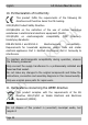
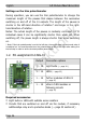
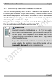
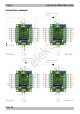
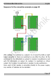
Table Of Contents
- Part A: General information
- Part B: LC-NG versions
- 1. LC-NG-01 "City Lighting"
- 2. LC-NG-02 "Residential buildings"
- 3. LC-NG-03 "Office and commercial buildings"
- 4. LC-NG-04 "Street lamps"
- 5. LC-NG-05 "Road traffic"
- 6. LC-NG-06 "Emergency vehicles"
- 7. LC-NG-07 "(Road) construction site"
- 8. LC-NG-08 "Fire station"
- 9. LC-NG-09 "Railway station"
- 10. LC-NG-10 "Workshop"
- 11. LC-NG-11 "Flickering flames & candle lights"
- 12. LC-NG-12 "Event"
- 13. LC-NG-13 "Chaser lights"
- 14. LC-NG-14 "Funfair lighting"

tams elektronik
English LC-Modules Next Generation
Settings on the trim potentiometer
During operation, you can use the trim potentiometer to change the
maximum length of the pauses that elapse between the successive
switching on and off of the 14 outputs. The length of the pauses is
shorter in the left-hand direction of rotation* and longer in the right-
hand direction of rotation.
Notes: The actual length of the pauses is randomly controlled, i.e. in
individual cases it can be significantly shorter than when set. When
switching off, the pause length is always shorter than when switching
on.
* Note: If the trim potentiometer is set to the left stop, the module goes into test mode when it
is switched on. You must therefore turn the potentiometer a little to the right after setting it to
the left stop in order to set the shortest possible pause length.
1.2. Pin assignment LC-NG-01
Output
Connection options
1 … 14
Light bulbs (→ page 24 )
1 … 14
LEDs (→ page 25 )
1 … 14
further modules LC-NG-01
(→ page 47)
1 … 14
other LC-NG modules or
following circuits
(→ page 33)
Required accessories
Light bulbs or LEDs with suitable series resistors
Circuits that are switched on and off via the module, if necessary
additionallya relay and a protective diode (→ page 33 section14 )
Page 46