
Instructions
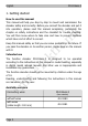
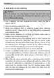
Table Of Contents
- 1. Getting started
- 2. Safety instructions
- 3. Safe and correct soldering
- 4. Operation overview
- 5. Technical specifications
- 6. Connections
- 7. Programming
- 8. Configuration variables and registers
- 9. Check list for troubleshooting
- 10. Guarantee bond
- 11. EU Declaration of Conformity
- 12. Declarations concerning the WEEE directive
- 13. The asterisks **

tams elektronik
FD-R Basic.3 English
Checking the package contents
Please make sure that your package contains:
one or five function decoders, depending on the version with or
without soldered connecting wires.
For mounting and connecting the decoder you need:
a soldering iron with temperature control and a thin tip and a deposit
stand or a controlled soldering station
a scraper, rag or sponge
a heat-resistant pad
a small pair of side cutters and wire strippers
tweezers and flat-nose pliers if necessary
electronic solder (preferably 0.5 to 0.8 mm diameter)
In order to connect a decoder without soldered connecting wires you
will also need wire. Recommended cross sections:
> 0,04 mm² for the connections to the function outputs,
> 0,05 mm² for the connections to the current collectors or slider
To bridge short current interruptions you need:
an electrolytic capacitor with a capacity of 100 to 470 µF and a proof
voltage of minimum 25 V or
a buffer circuit, e.g.
USV-mini 0.47 (capacity 0.47 F, item no. 70-02215 or 70-02216)
USV mini 1.0 (capacity 1.0 F, item no. 70-02225 or 70-02226)
USV mini 1.5 (capacity 1.5 F, item no 70-02235 or 70-02236).
To trigger switching operations automatically, you need:
a reed contact 1 x closing contact (e.g. item-no. 84-53110) or
a Hall-sensor (e.g. item-no. 84-53210)
permanent magnets (e.g. neodymium magnets Ø 3mm, thickness
= 2 mm, item-no. 84-53990)
Page 5