
Instructions


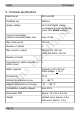

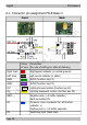
Table Of Contents
- 1. Getting started
- 2. Safety instructions
- 3. Safe and correct soldering
- 4. Operation overview
- 5. Technical specifications
- 6. Connections
- 7. Programming
- 8. Configuration variables and registers
- 9. Check list for troubleshooting
- 10. Guarantee bond
- 11. EU Declaration of Conformity
- 12. Declarations concerning the WEEE directive
- 13. The asterisks **

tams elektronik
English FD-R Basic.3
6.1. Connector pin assignment FD-R Basic.3
Front Back
Colour
of wire
Connection
(for use of settings in state of delivery)
Right track red Right current collector (or vehicle ground)
Left track black Left current collector (or slider)
AUX1 green AUX1 (function key F1)
AUX2 violet AUX2 (function key F2)
F0f white Lighting forward motion (function key F0)
F0r yellow Lighting backward motion (function key F0)
GND Negative pole (-) of buffer capacitor /
Earth connection IN
RC blue Common return conductor for all function
outputs (+)
Positive pole (+) of buffer capacitor
IN Switching input (back side)
Page 18