
Manual
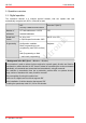
Table Of Contents
- 1. Getting started
- 2. Operation overview
- 3. Connections
- 3.1. Safety instructions
- 3.2. Safe and correct soldering
- 3.3. Avoiding irreparable damage to the decoder!
- 3.4. Pin assignment LD-G-43 | Front side
- 3.5. Pin assignment LD-G-43 | Rear side
- 3.6. Using decoders with interface connectors
- 3.7. Use of the LD-G-43 in locomotives with AC motor
- 3.8. Mounting decoders without interface
- 3.9. Connecting LEDs to the function outputs
- 3.10. Connecting inductive loads
- 3.11. Connecting the switching inputs
- 3.12. Connecting a backup capacitor or buffer circuit
- 3.13. Connection of a SUSI module
- 3.14. Completion
- 4. Programming
- 5. Configuration variables and registers
- 5.1. Overview configuration variables LD-G-43
- 5.2. Basic settings
- 5.3. Setting the address
- 5.4. Setting the motor control
- 5.5. Function mapping
- 5.6. Effects of the outputs
- 5.7. Settings for the switching inputs
- 5.8. RailCom and DCC-A settings
- 5.9. Settings for driving operation
- 5.10. Settings for analogue mode
- 5.11. Sensivity of the overload protection
- 5.12. Auxiliary functions
- 5.13. Information
- 6. Checklist for troubleshooting and error correction
- 7. Technical data
- 8. Warranty, EU conformity & WEEE

tams elektronik
LD-G-43 tams elektronik
2. Operation overview
2.1. Digital operation
The locomotive decoder is a multiple protocol decoder, that can operate with and
automatically recognise both DCC or Motorola formats.
DCC
according to NMRA and RCN-standard
Motorola II (MM II)
Number of
addresses
127 basic addresses or 10.239
extended addresses
255
Speed level
modes
14, 28 or 128
in 28/128 speed level mode: SDF*
MM II: 14 or 27b
Programming Configuration variables:
Direct programming on the
programming track (DCC conform)
or
PoM (Programming on Main
= main track programming)
Registers
* Background info: SDF (Speed – Direction – Function)
This procedure is used to reduce the time required to transmit speed, direction and function
commands to vehicle decoders in DCC format. Instead of transmitting the various commands
individually, all commands are summarised and transmitted in a single command.
The reduction in transmission time has a particularly positive effect on systems where a
large number of decoders with many functions are used.
The prerequisites for using this method are:
the use of a digital control unit that supports SDF
the installation of vehicle decoders that support SDF
setting the speed step mode 28 / 128 on the decoder.
8 | Operation overview