
Manual
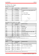
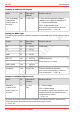
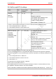
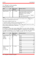
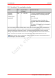
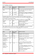
Table Of Contents
- 1. Getting started
- 2. Operation overview
- 3. Connections
- 3.1. Safety instructions
- 3.2. Safe and correct soldering
- 3.3. Avoiding irreparable damage to the decoder!
- 3.4. Pin assignment LD-G-43 | Front side
- 3.5. Pin assignment LD-G-43 | Rear side
- 3.6. Using decoders with interface connectors
- 3.7. Use of the LD-G-43 in locomotives with AC motor
- 3.8. Mounting decoders without interface
- 3.9. Connecting LEDs to the function outputs
- 3.10. Connecting inductive loads
- 3.11. Connecting the switching inputs
- 3.12. Connecting a backup capacitor or buffer circuit
- 3.13. Connection of a SUSI module
- 3.14. Completion
- 4. Programming
- 5. Configuration variables and registers
- 5.1. Overview configuration variables LD-G-43
- 5.2. Basic settings
- 5.3. Setting the address
- 5.4. Setting the motor control
- 5.5. Function mapping
- 5.6. Effects of the outputs
- 5.7. Settings for the switching inputs
- 5.8. RailCom and DCC-A settings
- 5.9. Settings for driving operation
- 5.10. Settings for analogue mode
- 5.11. Sensivity of the overload protection
- 5.12. Auxiliary functions
- 5.13. Information
- 6. Checklist for troubleshooting and error correction
- 7. Technical data
- 8. Warranty, EU conformity & WEEE

tams elektronik
tams elektronik LD-G-43
Braking behaviour with DC voltage
Name No. Input values
(Default)
Remarks and tips
Braking behaviour
with DC voltage
27 0, 16, 32, 48 (48) No braking with d.c. voltage 0
Braking with negative d.c. voltage 1
Braking with positive d.c. voltage 2
Tip: It is standard to switch over into analogue mode when applying a d.c. voltage at the rails. In case
that the decoder is run in a layout with a braking route based on applying a d.c. voltage (e.g. Märklin**-
braking route), the analogue recognition has to be disactivated (in CV 29) to ensure that the locomotive
reacts as expected on the braking route. The setting of the negative or positive d.c. voltage is related to
the right rail, as seen in the locomotive´s direction of motion.
Use of the ABC braking method
Name No. Input values
(Default)
Remarks and tips
ABC sensitivity 122 0 … 255 (10)
= Level of asymmetry of the track voltage,
which the decoder interprets as entering
an ABC braking section.
0 = highest sensitivity
255 = lowest sensitivity
Notes:
Boosters that do not have a 100 % symmetrical voltage or additional circuits on the track (e.g. track
occupancy detectors) can unintentionally generate an asymmetrical track voltage. To prevent the LD-G-
41 from interpreting this asymmetrical voltage on the normal track as entry into an ABC braking section,
the ABC sensitivity can be reduced.
For the decoder to react to the ABC braking section, the ABC braking procedure must be activated in CV
121.
Configuration variables and registers | 57