
Manual
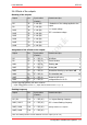
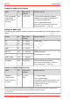
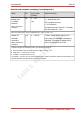
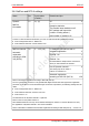
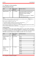
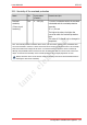
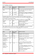
Table Of Contents
- 1. Getting started
- 2. Operation overview
- 3. Connections
- 3.1. Safety instructions
- 3.2. Safe and correct soldering
- 3.3. Avoiding irreparable damage to the decoder!
- 3.4. Pin assignment LD-G-43 | Front side
- 3.5. Pin assignment LD-G-43 | Rear side
- 3.6. Using decoders with interface connectors
- 3.7. Use of the LD-G-43 in locomotives with AC motor
- 3.8. Mounting decoders without interface
- 3.9. Connecting LEDs to the function outputs
- 3.10. Connecting inductive loads
- 3.11. Connecting the switching inputs
- 3.12. Connecting a backup capacitor or buffer circuit
- 3.13. Connection of a SUSI module
- 3.14. Completion
- 4. Programming
- 5. Configuration variables and registers
- 5.1. Overview configuration variables LD-G-43
- 5.2. Basic settings
- 5.3. Setting the address
- 5.4. Setting the motor control
- 5.5. Function mapping
- 5.6. Effects of the outputs
- 5.7. Settings for the switching inputs
- 5.8. RailCom and DCC-A settings
- 5.9. Settings for driving operation
- 5.10. Settings for analogue mode
- 5.11. Sensivity of the overload protection
- 5.12. Auxiliary functions
- 5.13. Information
- 6. Checklist for troubleshooting and error correction
- 7. Technical data
- 8. Warranty, EU conformity & WEEE

tams elektronik
LD-G-43 tams elektronik
5.9. Settings for driving operation
Setting the Packet Time Out
Name No. Input values
(Default)
Remarks and tips
Packet Time Out 11 2 … 255 (16) Time period between the failure of the
digital signal and the change to the
alternative operation (analogue
operation).
Increasing the input value by "1" extends
the time period by 10 ms.
Notes:
If automatic analogue recognition is active, the decoder will automatically switch to analogue mode if it
does not receive a digital signal during the set time.
If the decoder is supplied via a buffer circuit,
- the automatic analogue recognition in CV 29 should be deactivated and
- a low value for the Packet Time Out should be set (approx. 16).
This prevents the locomotive from continuing to run unplanned after the track voltage has been switched
off (e.g. during an emergency stop or a signal stop).
Consist operation
As a standard, in multiple units (consist operation) you can only control velocity and direction.
In CV 21 and 22 you can define additional functions to be switched when using the address
for multiple units defined in CV 19. If the value "0" is set, the function will continue to be
addressed only via the address set for the vehicle concerned in CV 1 or CV 17 and 18.
Name No. Input values
(Default)
Remarks and tips
Functions active in
consist
operation
(F1 to F8)
21 0 ... 255 (0) F1 on 1
F2 on 2
F3 on 4
F4 on 8
F5 on 16
F6 on 32
F7 on 64
F8 on 128
Functions active in
consist
operation
(F0, F9 to F12)
22 0 ... 63 (0) F0f on 1
F0r on 2
F9 on 4
F10 on 8
F11 on 16
F12 on 32
56 | Configuration variables and registers