
Manual
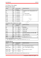
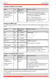
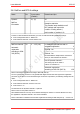
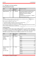
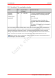
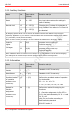
Table Of Contents
- 1. Getting started
- 2. Operation overview
- 3. Connections
- 3.1. Safety instructions
- 3.2. Safe and correct soldering
- 3.3. Avoiding irreparable damage to the decoder!
- 3.4. Pin assignment LD-G-43 | Front side
- 3.5. Pin assignment LD-G-43 | Rear side
- 3.6. Using decoders with interface connectors
- 3.7. Use of the LD-G-43 in locomotives with AC motor
- 3.8. Mounting decoders without interface
- 3.9. Connecting LEDs to the function outputs
- 3.10. Connecting inductive loads
- 3.11. Connecting the switching inputs
- 3.12. Connecting a backup capacitor or buffer circuit
- 3.13. Connection of a SUSI module
- 3.14. Completion
- 4. Programming
- 5. Configuration variables and registers
- 5.1. Overview configuration variables LD-G-43
- 5.2. Basic settings
- 5.3. Setting the address
- 5.4. Setting the motor control
- 5.5. Function mapping
- 5.6. Effects of the outputs
- 5.7. Settings for the switching inputs
- 5.8. RailCom and DCC-A settings
- 5.9. Settings for driving operation
- 5.10. Settings for analogue mode
- 5.11. Sensivity of the overload protection
- 5.12. Auxiliary functions
- 5.13. Information
- 6. Checklist for troubleshooting and error correction
- 7. Technical data
- 8. Warranty, EU conformity & WEEE

tams elektronik
tams elektronik LD-G-43
Kick time and automatic uncoupling ("uncoupling waltz")
Name No. Input values
(Default)
Remarks and tips
Kicking time
("moment-
function")
Setting common for
all outputs
99 0 ... 255
(32)
0 = shortest kick time
255 = longest kick time
(= 25.5 seconds)
Increasing the input value by "1" extends
the time period by 0.1 sec.
Note: The kick function must be activated for the output. (CV 55 - 62)
Voltage for
automatic
uncoupling
Setting common for
all outputs
110 0 ... 255 (5) = Motor voltage that is output to the
motor when the automatic uncoupling is
activated. The voltage is applied to the
motor for the time set in CV 99.
In order to trigger the "decoupling roller", the following must be set
the kick function must be activated for the output in CVs 55 ... 62.
a kick time > 0 must be set in CV 99
a voltage > 0 must be set in CV 110.
If a voltage = 0 is set in CV 110, only the voltage at the output is reduced to 0 after the set kick time, but
no back and forth movement of the locomotive is triggered.
Configuration variables and registers | 53