
Manual
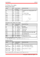
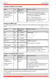
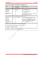
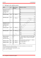
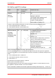
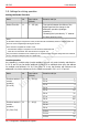
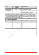
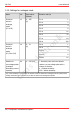
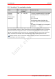
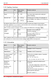
Table Of Contents
- 1. Getting started
- 2. Operation overview
- 3. Connections
- 3.1. Safety instructions
- 3.2. Safe and correct soldering
- 3.3. Avoiding irreparable damage to the decoder!
- 3.4. Pin assignment LD-G-43 | Front side
- 3.5. Pin assignment LD-G-43 | Rear side
- 3.6. Using decoders with interface connectors
- 3.7. Use of the LD-G-43 in locomotives with AC motor
- 3.8. Mounting decoders without interface
- 3.9. Connecting LEDs to the function outputs
- 3.10. Connecting inductive loads
- 3.11. Connecting the switching inputs
- 3.12. Connecting a backup capacitor or buffer circuit
- 3.13. Connection of a SUSI module
- 3.14. Completion
- 4. Programming
- 5. Configuration variables and registers
- 5.1. Overview configuration variables LD-G-43
- 5.2. Basic settings
- 5.3. Setting the address
- 5.4. Setting the motor control
- 5.5. Function mapping
- 5.6. Effects of the outputs
- 5.7. Settings for the switching inputs
- 5.8. RailCom and DCC-A settings
- 5.9. Settings for driving operation
- 5.10. Settings for analogue mode
- 5.11. Sensivity of the overload protection
- 5.12. Auxiliary functions
- 5.13. Information
- 6. Checklist for troubleshooting and error correction
- 7. Technical data
- 8. Warranty, EU conformity & WEEE

tams elektronik
LD-G-43 tams elektronik
Dimming up and down the outputs
Name No. Input values
(Default)
Remarks and tips
Time for dimming
up and down
Setting common for
all outputs
100
1...255 (10) = Time until the maximum voltage is
reached or the voltage is reduced to "0".
1 = shortest possible time
255 = longest possible time
Note: For the output, dimming up and down
must be switched on. → CV 55 - 62
Settings for MARs-Light
The warning light typical for American locomotives is generated when the CV values are set as
follows:
Output No. Input values
(Default)
Remarks and tips
F0f 55 0 ... 255 (0)
Flashing on 22
F0r 56 0 ... 255 (0)
...
AUX6 62 0 ... 255 (0)
F0f / F0r 101 1 ... 255 (20)
Flashing frequency 6
Setting common for 2 outputs
...
AUX5 / AUX6 104 1 ... 255 (20)
All outputs
100
1...255 (10)
Time for dimming up and down 2
Note: For the output, dimming up and down
must be switched on. → CV 55 - 62
Voltage for switching outputs on/off
Name No. Input values
(Default)
Remarks and tips
Voltage for
"output on/off"
Setting common for
all outputs
63
0 ... 255
(16)
0 = lowest voltage
255 = highest voltage
The setting only applies to the outputs for which
switching on/off has been activated when the
voltage set here is reached.
→ CV 55 … 62
By default, the output is switched off when the voltage is exceeded and switched on again when the
voltage falls below it. The function can be reversed by inverting the function.
(→ CV 55...62)
52 | Configuration variables and registers