
Manual
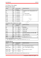
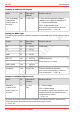
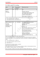
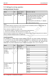
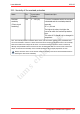
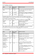
Table Of Contents
- 1. Getting started
- 2. Operation overview
- 3. Connections
- 3.1. Safety instructions
- 3.2. Safe and correct soldering
- 3.3. Avoiding irreparable damage to the decoder!
- 3.4. Pin assignment LD-G-43 | Front side
- 3.5. Pin assignment LD-G-43 | Rear side
- 3.6. Using decoders with interface connectors
- 3.7. Use of the LD-G-43 in locomotives with AC motor
- 3.8. Mounting decoders without interface
- 3.9. Connecting LEDs to the function outputs
- 3.10. Connecting inductive loads
- 3.11. Connecting the switching inputs
- 3.12. Connecting a backup capacitor or buffer circuit
- 3.13. Connection of a SUSI module
- 3.14. Completion
- 4. Programming
- 5. Configuration variables and registers
- 5.1. Overview configuration variables LD-G-43
- 5.2. Basic settings
- 5.3. Setting the address
- 5.4. Setting the motor control
- 5.5. Function mapping
- 5.6. Effects of the outputs
- 5.7. Settings for the switching inputs
- 5.8. RailCom and DCC-A settings
- 5.9. Settings for driving operation
- 5.10. Settings for analogue mode
- 5.11. Sensivity of the overload protection
- 5.12. Auxiliary functions
- 5.13. Information
- 6. Checklist for troubleshooting and error correction
- 7. Technical data
- 8. Warranty, EU conformity & WEEE

tams elektronik
tams elektronik LD-G-43
5.6. Effects of the outputs
Dimming of the outputs
Output No. Input values
(Default)
Remarks and tips
F0f 47
1...64 (64)
= Reduction of the voltage applied to the
output
1 = lowest voltage
255 = maximum voltage
F0r 48
1...64 (64)
AUX1 49
1...64 (64)
AUX2 50
1...64 (64)
AUX3 51
1...64 (64)
AUX4 52
1...64 (64)
AUX5 53
1...64 (64)
AUX6 54
1...64 (64)
Assignment of the effects to the outputs
Output No. Input values
(Default)
Remarks and tips
F0f 55 0 ... 255 (0) no effects 0
F0r 56 0 ... 255 (0) Invert function 1
AUX1 57 0 ... 255 (0)
Flashing on 2
AUX2 58 0 ... 255 (0)
Kicking on 4
AUX3 59 0 ... 255 (0)
Successive dimming up and down off 8
AUX4 60 0 ... 255 (0)
Fire simulation on 16
AUX5 61 0 ... 255 (0)
Output on/off at the
voltage defined in CV 63 32
AUX6 62 0 ... 255 (0)
Example: Alternating flashing with AUX1 and AUX2:
→ Input value for AUX1: CV 59 = 2 | Input value for AUX2: CV 60 = 3 (1 + 2)
Flashing frequency
Output No. Input values
(Default)
Remarks and tips
F0f / F0r 101 1 ... 255 (20)
1 = highest flashing frequency
255 = lowest flashing frequency
Setting common for 2 outputs
AUX1 / AUX 2 102 1 ... 255 (20)
AUX3 / AUX4 103 1 ... 255 (20)
AUX5 / AUX6 104 1 ... 255 (20)
Note: The flashing function must be switched on for the output. (CV 55 - 62)
Configuration variables and registers | 51