
Manual

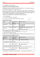
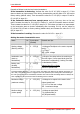
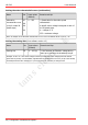
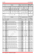
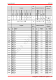
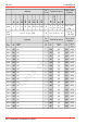
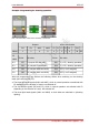
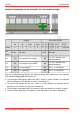
Table Of Contents
- 1. Getting started
- 2. Operation overview
- 3. Connections
- 3.1. Safety instructions
- 3.2. Safe and correct soldering
- 3.3. Avoiding irreparable damage to the decoder!
- 3.4. Pin assignment LD-G-43 | Front side
- 3.5. Pin assignment LD-G-43 | Rear side
- 3.6. Using decoders with interface connectors
- 3.7. Use of the LD-G-43 in locomotives with AC motor
- 3.8. Mounting decoders without interface
- 3.9. Connecting LEDs to the function outputs
- 3.10. Connecting inductive loads
- 3.11. Connecting the switching inputs
- 3.12. Connecting a backup capacitor or buffer circuit
- 3.13. Connection of a SUSI module
- 3.14. Completion
- 4. Programming
- 5. Configuration variables and registers
- 5.1. Overview configuration variables LD-G-43
- 5.2. Basic settings
- 5.3. Setting the address
- 5.4. Setting the motor control
- 5.5. Function mapping
- 5.6. Effects of the outputs
- 5.7. Settings for the switching inputs
- 5.8. RailCom and DCC-A settings
- 5.9. Settings for driving operation
- 5.10. Settings for analogue mode
- 5.11. Sensivity of the overload protection
- 5.12. Auxiliary functions
- 5.13. Information
- 6. Checklist for troubleshooting and error correction
- 7. Technical data
- 8. Warranty, EU conformity & WEEE

tams elektronik
LD-G-43 tams elektronik
Example: Programming for rear end signal "off" with coupled carriages
Hint: The connection of the return conductor is not shown.
Outputs off/on with function
F0f F0r AUX1 AUX2 F0 F1 F2 F3 F4 … F28 ---
Values 1 2 4 8 0 1 2 3 4 … 28 255
CV
name
CV-No. Set value CV-No. Set value
F0 f 257 5 (outputs F0f and AUX1) 260
5 (= F5 / operation with
attached wagons)
F0 r 261 10 (outputs F0r and AUX2) 264
5 (= F5 / operation with
attached wagons)
F3 f 281 4 (output AUX1) 284 255 (= no F assigned)
F3 r 285 2 ( output F0r) 288 255 (= no F assigned)
With this programming you achieve the following effects when switching on the operation
with attached wagons (here with function F5):
The three-light head signals (AUX1 and AUX2), which in normal operation are switched
with F0 depending on the direction of travel, are switched off.
The end-of-train signals (F0f and F0r), which in normal operation are switched with F0
depending on the direction of travel, are switched off.
The three-light head signal (AUX1) is switched on when the direction of travel is "forward".
The end-of-train signal (F0r) is switched on when the direction of travel is "backwards".
50 | Configuration variables and registers