
Manual

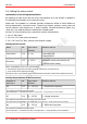
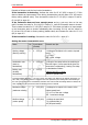
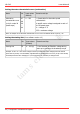
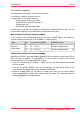
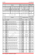
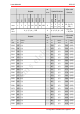
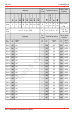
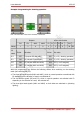
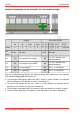
Table Of Contents
- 1. Getting started
- 2. Operation overview
- 3. Connections
- 3.1. Safety instructions
- 3.2. Safe and correct soldering
- 3.3. Avoiding irreparable damage to the decoder!
- 3.4. Pin assignment LD-G-43 | Front side
- 3.5. Pin assignment LD-G-43 | Rear side
- 3.6. Using decoders with interface connectors
- 3.7. Use of the LD-G-43 in locomotives with AC motor
- 3.8. Mounting decoders without interface
- 3.9. Connecting LEDs to the function outputs
- 3.10. Connecting inductive loads
- 3.11. Connecting the switching inputs
- 3.12. Connecting a backup capacitor or buffer circuit
- 3.13. Connection of a SUSI module
- 3.14. Completion
- 4. Programming
- 5. Configuration variables and registers
- 5.1. Overview configuration variables LD-G-43
- 5.2. Basic settings
- 5.3. Setting the address
- 5.4. Setting the motor control
- 5.5. Function mapping
- 5.6. Effects of the outputs
- 5.7. Settings for the switching inputs
- 5.8. RailCom and DCC-A settings
- 5.9. Settings for driving operation
- 5.10. Settings for analogue mode
- 5.11. Sensivity of the overload protection
- 5.12. Auxiliary functions
- 5.13. Information
- 6. Checklist for troubleshooting and error correction
- 7. Technical data
- 8. Warranty, EU conformity & WEEE

tams elektronik
tams elektronik LD-G-43
5.5. Function mapping
The assignment of the actions controlled by the decoder
switching the function outputs on and off
(de)activation of the special functions
Uninterruptible power supply (UPS)
Start/Stop with a function (Stop with F)
Shunting gear (SG)
Acceleration and brake delay (ABD)
to the functions is carried out according to RailCommunity standard RCN-227. Note: The use
of the function mapping is not possible with pure Motorola control units.
Basic settings for using the function mapping
To get access to the corresponding memory area (the so-called "page"), the values for
"Function mapping" must be set in CV 31 and 32 (= default values).
Name No. Input values (Default) Remarks and tips
Index for
higher pages
31 0 ... 255 (0) Function mapping active 0
32 0 ... 255 (42) Function mapping active 42
Configuration variables for function mapping
According to RCN-227, eight configuration variables (CVs) are assigned to each function (F0 to
F28): four each for forward ("f") and reverse ("r"). Six of these are used for the LD-G-43
locomotive decoder (3 for forward and 3 for reverse):
2 CVs for the outputs (F0f, F0r, AUX1 ... AUX6): Here you set which outputs are switched
with the function.
4 CVs for the special functions: Here you set separately for each driving direction with
which function the special functions are activated / deactivated.
Switch-off function: Here you can define a function with which you can switch off the
actions assigned to the function when switching on. The value "255" determines that the
actions are switched off with no function.
Configuration variables and registers | 45