
Manual

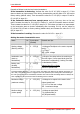
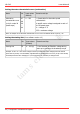
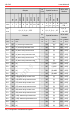
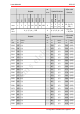
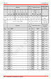
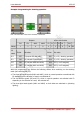
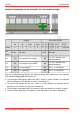
Table Of Contents
- 1. Getting started
- 2. Operation overview
- 3. Connections
- 3.1. Safety instructions
- 3.2. Safe and correct soldering
- 3.3. Avoiding irreparable damage to the decoder!
- 3.4. Pin assignment LD-G-43 | Front side
- 3.5. Pin assignment LD-G-43 | Rear side
- 3.6. Using decoders with interface connectors
- 3.7. Use of the LD-G-43 in locomotives with AC motor
- 3.8. Mounting decoders without interface
- 3.9. Connecting LEDs to the function outputs
- 3.10. Connecting inductive loads
- 3.11. Connecting the switching inputs
- 3.12. Connecting a backup capacitor or buffer circuit
- 3.13. Connection of a SUSI module
- 3.14. Completion
- 4. Programming
- 5. Configuration variables and registers
- 5.1. Overview configuration variables LD-G-43
- 5.2. Basic settings
- 5.3. Setting the address
- 5.4. Setting the motor control
- 5.5. Function mapping
- 5.6. Effects of the outputs
- 5.7. Settings for the switching inputs
- 5.8. RailCom and DCC-A settings
- 5.9. Settings for driving operation
- 5.10. Settings for analogue mode
- 5.11. Sensivity of the overload protection
- 5.12. Auxiliary functions
- 5.13. Information
- 6. Checklist for troubleshooting and error correction
- 7. Technical data
- 8. Warranty, EU conformity & WEEE

tams elektronik
LD-G-43 tams elektronik
5.4. Setting the motor control
Optimisation of the driving characteristics
By adjusting the load control and the motor characteristics curve the decoder is adapted to
the individual characteristics of the locomotive motor.
Please note: The installation of a decoder generally increases the effects of vehicle defects on
driving characteristics. Locomotive motor, brushes and collector, gearbox, moving parts and
current collectors must therefore be in perfect condition. Electrical interference signals (e.g.
"brush fire") can massively affect the transmission of digital signals.
Set the CVs in the following order to optimize the driving characteristics:
1. CV 112 "Gain factor"
2. CV 113 to 115 "Load control parameters"
3. CV 2, CV 5 and CV 6 "Start, maximum and medium voltage"
Setting the load control
Name No. Input values
(Default)
Remarks and tips
Load control 116 0, 1 (1) Load control off 0
Load control on 1
Gain factor
112 1...15 (5) Adaptation of the load control to the
individual motor voltage
Note: The adaptation of CV 112 is only necessary if
- the maximum speed of the locomotive is already reached at a low speed level or
- is not reached at the highest speed level.
Change the value only gradually until the desired maximum speed is reached at the highest speed level.
Setting the parameters of the load control
Parameter of
load control
No. Input values
(Default)
Remarks and tips
KP 113 0 ... 255 (32) = Proportional component
The parameter KP defines the basic speed.
A too small value → locomotive too slow. A too high value → heavy shuttering of the locomotive.
KI 114 0 ... 255 (5) = Integral component
The parameter KI provides the fine tuning of the load control.
The value has to be adjusted in very small steps. A too high value → heavy shuttering of the locomotive.
KD 115 0 ... 255 (4) = Differential component
The parameter KP defines the basic speed.
A too small value → locomotive too slow. A too high value → heavy shuttering of the locomotive.
42 | Configuration variables and registers