
Manual
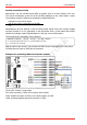
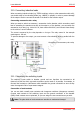
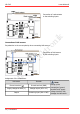
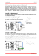
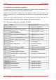
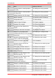
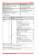
Table Of Contents
- 1. Getting started
- 2. Operation overview
- 3. Connections
- 3.1. Safety instructions
- 3.2. Safe and correct soldering
- 3.3. Avoiding irreparable damage to the decoder!
- 3.4. Pin assignment LD-G-43 | Front side
- 3.5. Pin assignment LD-G-43 | Rear side
- 3.6. Using decoders with interface connectors
- 3.7. Use of the LD-G-43 in locomotives with AC motor
- 3.8. Mounting decoders without interface
- 3.9. Connecting LEDs to the function outputs
- 3.10. Connecting inductive loads
- 3.11. Connecting the switching inputs
- 3.12. Connecting a backup capacitor or buffer circuit
- 3.13. Connection of a SUSI module
- 3.14. Completion
- 4. Programming
- 5. Configuration variables and registers
- 5.1. Overview configuration variables LD-G-43
- 5.2. Basic settings
- 5.3. Setting the address
- 5.4. Setting the motor control
- 5.5. Function mapping
- 5.6. Effects of the outputs
- 5.7. Settings for the switching inputs
- 5.8. RailCom and DCC-A settings
- 5.9. Settings for driving operation
- 5.10. Settings for analogue mode
- 5.11. Sensivity of the overload protection
- 5.12. Auxiliary functions
- 5.13. Information
- 6. Checklist for troubleshooting and error correction
- 7. Technical data
- 8. Warranty, EU conformity & WEEE

tams elektronik
tams elektronik LD-G-43
CV-Nr. Name Anleitung Abschnitt
21 Functions active in consist operation
(F1 to F8)
5.9. Settings for driving operation
22 Functions active in consist operation
(F0, F9 to F12)
5.9. Settings for driving operation
27 Braking behaviour with DC voltage 5.9. Settings for driving operation
28 RailCom channels 5.8. RailCom and DCC-A settings
29 Configuration data 1 5.2. Basic settings
31 und 32 Index for higher CV-Pages 5.5. Function mapping
47...54 Dimming of the outputs 5.6. Effects of the outputs
55...62 Assignment of the effects to the
outputs
5.6. Effects of the outputs
63 Dimming up and down the outputs 5.6. Effects of the outputs
64 Reaction to overvoltage pulses
(analogue alternating current systems)
5.10. Settings for analogue mode
65 Starting kick 5.4. Setting the motor control
67...94 Alternative characteristic curve
(only for mode 28 speed steps)
5.4. Setting the motor control
96 Method for function assignment 5.13. Information
97
98
Minimum switch-on time of the
switching inputs
5.7. Settings for the switching inputs
99 Kicking time ("moment-function") 5.6. Effects of the outputs
100 Dimming up and down the outputs 5.6. Effects of the outputs
101...104 Flashing frequency 5.6. Effects of the outputs
105
107
Assignment of the functions to the
switching inputs F0 … F7
5.7. Settings for the switching inputs
106
108
Assignment of the functions to the
switching inputs F8 … F15
5.7. Settings for the switching inputs
109 Overload sensitivity
("Short-circuit sensitivity")
5.11. Sensivity of the overload
protection
110 Voltage for automatic uncoupling 5.6. Effects of the outputs
112 Gain factor for load control 5.4. Setting the motor control
113 Parameter of load control KP 5.4. Setting the motor control
114 Parameter of load control KI 5.4. Setting the motor control
Configuration variables and registers | 39