
Manual
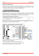
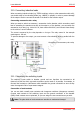
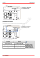
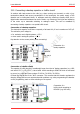
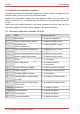
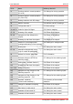
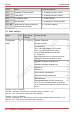
Table Of Contents
- 1. Getting started
- 2. Operation overview
- 3. Connections
- 3.1. Safety instructions
- 3.2. Safe and correct soldering
- 3.3. Avoiding irreparable damage to the decoder!
- 3.4. Pin assignment LD-G-43 | Front side
- 3.5. Pin assignment LD-G-43 | Rear side
- 3.6. Using decoders with interface connectors
- 3.7. Use of the LD-G-43 in locomotives with AC motor
- 3.8. Mounting decoders without interface
- 3.9. Connecting LEDs to the function outputs
- 3.10. Connecting inductive loads
- 3.11. Connecting the switching inputs
- 3.12. Connecting a backup capacitor or buffer circuit
- 3.13. Connection of a SUSI module
- 3.14. Completion
- 4. Programming
- 5. Configuration variables and registers
- 5.1. Overview configuration variables LD-G-43
- 5.2. Basic settings
- 5.3. Setting the address
- 5.4. Setting the motor control
- 5.5. Function mapping
- 5.6. Effects of the outputs
- 5.7. Settings for the switching inputs
- 5.8. RailCom and DCC-A settings
- 5.9. Settings for driving operation
- 5.10. Settings for analogue mode
- 5.11. Sensivity of the overload protection
- 5.12. Auxiliary functions
- 5.13. Information
- 6. Checklist for troubleshooting and error correction
- 7. Technical data
- 8. Warranty, EU conformity & WEEE

tams elektronik
LD-G-43 tams elektronik
5. Configuration variables and registers
The following lists shows all configuration variables (for the DCC format) and registers (for the
Motorola format), that can be set for the locomotive decoder.
Registers and configuration variables (CVs) have identical numbers, they are shown in the
tables in the column "No.". The defaults are those values set in the state of delivery and after
a reset.
Please note: With variables destined to set several parameters, the input value has to be
calculated by adding the numerical values assigned to the desired parameters.
5.1. Overview configuration variables LD-G-43
CV-Nr. Name Anleitung Abschnitt
1 Basic address 5.3. Setting the address
2 Starting voltage (starting velocity 5.4. Setting the motor control
3 Acceleration rate
(start-up deceleration)
5.4. Setting the motor control
4 Braking rate (braking deceleration) 5.4. Setting the motor control
5 Maximum voltage (maximum velocity) 5.4. Setting the motor control
6 Medium voltage (center speed) 5.4. Setting the motor control
7 Version 5.13. Information
8 Reset | Manufacturer 5.12. Auxiliary functions
5.13. Information
10 Dynamic RailCom information 5.8. RailCom and DCC-A settings
11 Packet Time Out 5.9. Settings for driving operation
12 Permitted modes of operation 5.13. Information
13 Functions active in analogue mode
(F1 to F8)
5.10. Settings for analogue mode
14 Functions active in analogue mode
(F0, F9 to F12)
5.10. Settings for analogue mode
15 and 16 Decoder lock 5.12. Auxiliary functions
17 and 18 Extended address 5.3. Setting the address
19 Consist address 5.3. Setting the address
20 2nd Motorola address 5.3. Setting the address
38 | Configuration variables and registers