
Manual
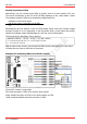
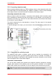
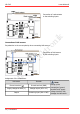
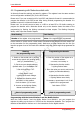
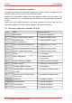
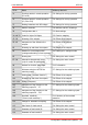
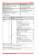
Table Of Contents
- 1. Getting started
- 2. Operation overview
- 3. Connections
- 3.1. Safety instructions
- 3.2. Safe and correct soldering
- 3.3. Avoiding irreparable damage to the decoder!
- 3.4. Pin assignment LD-G-43 | Front side
- 3.5. Pin assignment LD-G-43 | Rear side
- 3.6. Using decoders with interface connectors
- 3.7. Use of the LD-G-43 in locomotives with AC motor
- 3.8. Mounting decoders without interface
- 3.9. Connecting LEDs to the function outputs
- 3.10. Connecting inductive loads
- 3.11. Connecting the switching inputs
- 3.12. Connecting a backup capacitor or buffer circuit
- 3.13. Connection of a SUSI module
- 3.14. Completion
- 4. Programming
- 5. Configuration variables and registers
- 5.1. Overview configuration variables LD-G-43
- 5.2. Basic settings
- 5.3. Setting the address
- 5.4. Setting the motor control
- 5.5. Function mapping
- 5.6. Effects of the outputs
- 5.7. Settings for the switching inputs
- 5.8. RailCom and DCC-A settings
- 5.9. Settings for driving operation
- 5.10. Settings for analogue mode
- 5.11. Sensivity of the overload protection
- 5.12. Auxiliary functions
- 5.13. Information
- 6. Checklist for troubleshooting and error correction
- 7. Technical data
- 8. Warranty, EU conformity & WEEE

tams elektronik
tams elektronik LD-G-43
4.2. Programming with Motorola central units
In Motorola format the settings are saved in registers. The registers have the same numbers
as the configuration variables (CVs) for the DCC format.
Please note: If you use a central unit for both DCC and Motorola format it is recommended to
program the decoder in the DCC format. After having finished programming the decoder it is
possible to control it in Motorola format as well.
Please note: You should connect a lamp or a LED to at least F0f or F0r before starting to
program the decoder with a Motorola central unit, as the decoder shows the status of the
programming by flashing the lighting connected to these outputs. The flashing frequency
shows, which input the decoder expects:
Slow flashing Fast flashing
Number of the register to be programmed Value of the register to be programmed
Put the vehicle on a track oval or a track section connected to the central unit’s track output (not
to the connection for the programming track). Make sure no other vehicle than the one you
intend to program is set on the track as the decoder inside this vehicle might be programmed as
well.
Starting
the programming mode
Programming the decoder
1. Switch on the central unit or perform
a reset at the central unit (pushing "stop"
and "go") simultaneously.
2. Set the current decoder address
(default value: 3) or the address "80".
3. Set all functions to "off".
4. Push button "stop"
→ switch off the track voltage.
5. Operate the direction switch
and hold it in that position.
Push the button "go" at once.
6. As soon as the lighting flashes,
release the direction switch.
1. Enter the number of the register as a
Motorola-address.
If necessary: with a leading "0".
2. Operate the direction switch.
→ Lighting flashes faster.
3. Enter the value you want to set into the
register (as Motorola-address).
4. Operate the direction switch.
→ Lighting flashes more slowly.
If necessary: repeat steps 1 to 4 for all
registers to be programmed.
Push button "STOP".
→ Start of programming mode → End of programming mode
Programming with the Central Station I and the Mobile Station
With the Central Station I and the Mobile Station from Märklin** you can program the
registers by calling up the item no. 29750 from the locomotive database. Then program the
decoder as described for this item no. in the instructions for the digital controls.
Programming | 37