
Manual
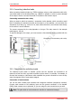
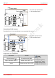
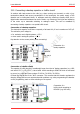
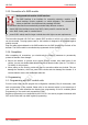
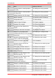
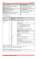
Table Of Contents
- 1. Getting started
- 2. Operation overview
- 3. Connections
- 3.1. Safety instructions
- 3.2. Safe and correct soldering
- 3.3. Avoiding irreparable damage to the decoder!
- 3.4. Pin assignment LD-G-43 | Front side
- 3.5. Pin assignment LD-G-43 | Rear side
- 3.6. Using decoders with interface connectors
- 3.7. Use of the LD-G-43 in locomotives with AC motor
- 3.8. Mounting decoders without interface
- 3.9. Connecting LEDs to the function outputs
- 3.10. Connecting inductive loads
- 3.11. Connecting the switching inputs
- 3.12. Connecting a backup capacitor or buffer circuit
- 3.13. Connection of a SUSI module
- 3.14. Completion
- 4. Programming
- 5. Configuration variables and registers
- 5.1. Overview configuration variables LD-G-43
- 5.2. Basic settings
- 5.3. Setting the address
- 5.4. Setting the motor control
- 5.5. Function mapping
- 5.6. Effects of the outputs
- 5.7. Settings for the switching inputs
- 5.8. RailCom and DCC-A settings
- 5.9. Settings for driving operation
- 5.10. Settings for analogue mode
- 5.11. Sensivity of the overload protection
- 5.12. Auxiliary functions
- 5.13. Information
- 6. Checklist for troubleshooting and error correction
- 7. Technical data
- 8. Warranty, EU conformity & WEEE

tams elektronik
tams elektronik LD-G-43
3.12. Connecting a backup capacitor or buffer circuit
In sections with bad contact to the rails (e.g. when running over turnouts) or with a (e.g.
construction-related) bad current consumption of the locomotive, the power supply of the
decoder can be interrupted briefly. In analogue mode the effects are usually small, but in
digital mode massive disturbances can be the result: e.g. flickering of the lights and stuttering
of the motor up to automatic switching to analogue mode. This can be remedied by
connecting a backup capacitor or a special buffer circuit.
Connection of a backup capacitor
The electrolytic capacitor must have a capacity of at least 100 µF and a maximum of 470 µF.
The minimum proof voltage is:
for exclusive use in digital systems: > 25 V
when used in analogue systems: > 35 V
Pay attention to the correct polarity when connecting!
Connection of a
backup capacitor
Connection of a buffer circuit
The capacity of buffer circuits is considerably larger than that of backup capacitors (e.g. UPS-
mini with 0.47 F, 1.0 F or 1.5 F). Use a buffer circuit according to RCN-530 which is connected
to ground, e.g. UPS-mini (item numbers 70-0221x, 70-0222x, 70-0223x).
Connect the control line to the "UPS" connector. This ensures that the decoder regulates the
charging current and current output and avoids problems e.g. when programming the decoder
on the programming track or when switching on the system.
Connection of a
buffer circuit according to
RCN-530 (e.g. UPS-mini)
Connections | 35