
Manual
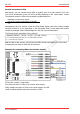
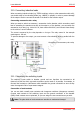
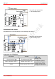
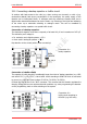
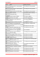
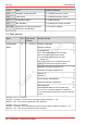
Table Of Contents
- 1. Getting started
- 2. Operation overview
- 3. Connections
- 3.1. Safety instructions
- 3.2. Safe and correct soldering
- 3.3. Avoiding irreparable damage to the decoder!
- 3.4. Pin assignment LD-G-43 | Front side
- 3.5. Pin assignment LD-G-43 | Rear side
- 3.6. Using decoders with interface connectors
- 3.7. Use of the LD-G-43 in locomotives with AC motor
- 3.8. Mounting decoders without interface
- 3.9. Connecting LEDs to the function outputs
- 3.10. Connecting inductive loads
- 3.11. Connecting the switching inputs
- 3.12. Connecting a backup capacitor or buffer circuit
- 3.13. Connection of a SUSI module
- 3.14. Completion
- 4. Programming
- 5. Configuration variables and registers
- 5.1. Overview configuration variables LD-G-43
- 5.2. Basic settings
- 5.3. Setting the address
- 5.4. Setting the motor control
- 5.5. Function mapping
- 5.6. Effects of the outputs
- 5.7. Settings for the switching inputs
- 5.8. RailCom and DCC-A settings
- 5.9. Settings for driving operation
- 5.10. Settings for analogue mode
- 5.11. Sensivity of the overload protection
- 5.12. Auxiliary functions
- 5.13. Information
- 6. Checklist for troubleshooting and error correction
- 7. Technical data
- 8. Warranty, EU conformity & WEEE

tams elektronik
!
tams elektronik LD-G-43
3.10. Connecting inductive loads
When connecting inductive loads (e.g. TELEX couplings, relays or other accessories with coils),
you should switch a free-wheeling diode (e.g. 1N400x) in parallel, in order to prevent damage
at the output. Check to connect the anode of the diode to the function output.
Connecting accessories via a relay
When you want to switch an accessory / accessories via the decoder, which connection would
lead to exceeding the maximum current at the output or of the decoder, you can switch the
accessories via a relay (e.g. 1xUm 1A 12V, item-number 84-61010) and connect them directly
to the vehicle´s current collector.
The current consumed by the relay depends on its type. The relay named in the example
needs approx. 100 mA.
To prevent damage to the output, you must connect a free-wheeling diode in parallel with the
relay.
Connection of an accessory via a relay
3.11. Connecting the switching inputs
The switching inputs switch to decoder ground and can therefore be connected to all
(external) circuits via which a ground connection can be made. It is possible, for example, to
connect reed contacts or Hall sensors which establish the ground connection as soon as they
enter the magnetic field of a permanent magnet.
Connection of reed contacts
You can use both normally open contacts and changeover switches (changeover contacts).
Connect reed contacts to the switching input and the ground connection of the decoder
(GND). Reed contacts are not polarized, so you can assign the two connections as you wish.
Note: The glass bulbs of reed contacts are sensitive to mechanical damage!
Connections | 33