
Manual
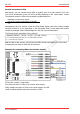
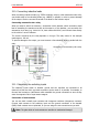
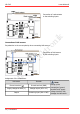
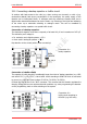
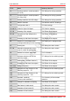
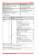
Table Of Contents
- 1. Getting started
- 2. Operation overview
- 3. Connections
- 3.1. Safety instructions
- 3.2. Safe and correct soldering
- 3.3. Avoiding irreparable damage to the decoder!
- 3.4. Pin assignment LD-G-43 | Front side
- 3.5. Pin assignment LD-G-43 | Rear side
- 3.6. Using decoders with interface connectors
- 3.7. Use of the LD-G-43 in locomotives with AC motor
- 3.8. Mounting decoders without interface
- 3.9. Connecting LEDs to the function outputs
- 3.10. Connecting inductive loads
- 3.11. Connecting the switching inputs
- 3.12. Connecting a backup capacitor or buffer circuit
- 3.13. Connection of a SUSI module
- 3.14. Completion
- 4. Programming
- 5. Configuration variables and registers
- 5.1. Overview configuration variables LD-G-43
- 5.2. Basic settings
- 5.3. Setting the address
- 5.4. Setting the motor control
- 5.5. Function mapping
- 5.6. Effects of the outputs
- 5.7. Settings for the switching inputs
- 5.8. RailCom and DCC-A settings
- 5.9. Settings for driving operation
- 5.10. Settings for analogue mode
- 5.11. Sensivity of the overload protection
- 5.12. Auxiliary functions
- 5.13. Information
- 6. Checklist for troubleshooting and error correction
- 7. Technical data
- 8. Warranty, EU conformity & WEEE

tams elektronik
LD-G-43 tams elektronik
Parallel connection of LEDs
Alternatively, you can connect several LEDs in parallel, each via a series resistor of its own.
The current consumption is max. 20 mA for all LEDs, depending on the series resistor´s value.
The maximum number of LEDs to be connected in parallel results from
maximum current at the output
- sum of the current consumption of all LEDs
> 0
Advantageous with this solution is that the LEDs already lighten when their forward voltage
has been reached (2 to 4 V, depending on the fluorescent colour), which makes this solution
suitable for analogue mode. Disadvantageous is the high current consumption.
The formula for the calculation of the resistor is:
required R
V
[Ohm] = ( U
B
[V] – U
F
[V] ) / (I
F
[mA] x 0.001)
U
B
= operating voltage (peak value) | U
F
= forward voltage of the LED
I
F
= current with max. luminosity
Tip: In order to save current, you can limit the LEDs´current consumption to 10 mA, which
normally does not cause a visible loss of luminance.
Examples for connecting LEDs to the function outputs
F0f and F0r: forward / reverse light
F0f: serial connection of LEDs via a common series resistor
AUX4: parallel connection of LEDs via one series resistor per LED
AUX6: combined parallel and serial connection of LEDs
32 | Connections