
Manual
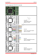
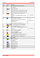
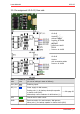
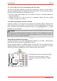
Table Of Contents
- 1. Getting started
- 2. Operation overview
- 3. Connections
- 3.1. Safety instructions
- 3.2. Safe and correct soldering
- 3.3. Avoiding irreparable damage to the decoder!
- 3.4. Pin assignment LD-G-43 | Front side
- 3.5. Pin assignment LD-G-43 | Rear side
- 3.6. Using decoders with interface connectors
- 3.7. Use of the LD-G-43 in locomotives with AC motor
- 3.8. Mounting decoders without interface
- 3.9. Connecting LEDs to the function outputs
- 3.10. Connecting inductive loads
- 3.11. Connecting the switching inputs
- 3.12. Connecting a backup capacitor or buffer circuit
- 3.13. Connection of a SUSI module
- 3.14. Completion
- 4. Programming
- 5. Configuration variables and registers
- 5.1. Overview configuration variables LD-G-43
- 5.2. Basic settings
- 5.3. Setting the address
- 5.4. Setting the motor control
- 5.5. Function mapping
- 5.6. Effects of the outputs
- 5.7. Settings for the switching inputs
- 5.8. RailCom and DCC-A settings
- 5.9. Settings for driving operation
- 5.10. Settings for analogue mode
- 5.11. Sensivity of the overload protection
- 5.12. Auxiliary functions
- 5.13. Information
- 6. Checklist for troubleshooting and error correction
- 7. Technical data
- 8. Warranty, EU conformity & WEEE

tams elektronik
!
tams elektronik LD-G-43
3.7. Use of the LD-G-43 in locomotives with AC motor
The LD-G-43 has been designed to control direct current (DC) motors, for that reason it
cannot be connected directly to alternating current (AC) motors. You can control AC motors
with the LD-G-43 and benefit of the load control when
mounting a load control adapter (e.g. item number 70-02105 or 70-02106) between AC
motor and decoder or
replacing the field coil of the AC motor by a permanent magnet (e.g. item number
70-04100, 70-04200 or 70-04300).
3.8. Mounting decoders without interface
Locate the position for the decoder after opening the locomotive housing. Disconnect the
motor from the rail current collectors or the change-over switch from the motor and rails if you
have a locomotive with electronic change-over switch. The change-over switch is no longer
necessary, you can remove it.
Caution:
The interference suppression devices mounted to the motor or the connecting wire must not
be removed! Motor and interference suppression devices are one unit. If even one part is
removed, it can cause extreme interference!
Connecting the decoder to the motor
Connect the decoder to the motor and the current collectors or the slider / vehicle ground
(track left and right) according to the connection drawing.
Only for analogue operation on 2-rail DC systems: If the direction of travel of the locomotive in
analogue operation does not match the direction of travel set on the transformer, you must
change the connections leading to the current collectors (track right and left).
Connecting the DC motor and the power supply
Track left = left current collector or slider
Track right = right current collector or vehicle
ground
Connections | 29