
Manual
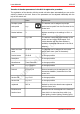
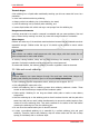
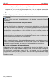
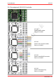
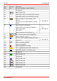
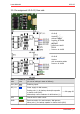
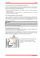
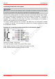
Table Of Contents
- 1. Getting started
- 2. Operation overview
- 3. Connections
- 3.1. Safety instructions
- 3.2. Safe and correct soldering
- 3.3. Avoiding irreparable damage to the decoder!
- 3.4. Pin assignment LD-G-43 | Front side
- 3.5. Pin assignment LD-G-43 | Rear side
- 3.6. Using decoders with interface connectors
- 3.7. Use of the LD-G-43 in locomotives with AC motor
- 3.8. Mounting decoders without interface
- 3.9. Connecting LEDs to the function outputs
- 3.10. Connecting inductive loads
- 3.11. Connecting the switching inputs
- 3.12. Connecting a backup capacitor or buffer circuit
- 3.13. Connection of a SUSI module
- 3.14. Completion
- 4. Programming
- 5. Configuration variables and registers
- 5.1. Overview configuration variables LD-G-43
- 5.2. Basic settings
- 5.3. Setting the address
- 5.4. Setting the motor control
- 5.5. Function mapping
- 5.6. Effects of the outputs
- 5.7. Settings for the switching inputs
- 5.8. RailCom and DCC-A settings
- 5.9. Settings for driving operation
- 5.10. Settings for analogue mode
- 5.11. Sensivity of the overload protection
- 5.12. Auxiliary functions
- 5.13. Information
- 6. Checklist for troubleshooting and error correction
- 7. Technical data
- 8. Warranty, EU conformity & WEEE

tams elektronik
!
!
LD-G-43 tams elektronik
Info: Ground connections, voltage outputs, return conductor
At the locomotive decoder LD-G-43 some connections are available on the front side
(according to the definition for the PluX interface) as well as additionally on the rear side:
Colour of
wire
Front
side
Rear
side
Ground connection for reed contacts / hall sensors braun X5 GND
Minus pole (-) for backup capacitor or buffer circuit (UPS)
Power supply for Hall sensors blau X6, X9 RC / V+
Positive pole (+) for backup capacitor or buffer circuit (UPS)
Return conductor (RC) for all functions (+)
The relevant connections on the front and rear are each interconnected and can therefore be
assigned according to practical requirements. It is recommended to use the connections on
the decoder rear for the connections of reed contacts, Hall sensors, backup electrolytic
capacitors and/or a buffer circuit.
3.6. Using decoders with interface connectors
Many newer locomotives with DC motors already have an interface installed at the factory. By
using a decoder with a suitable interface you save the cutting of the connections and
soldering work on the locomotive.
The locomotive decoder LD-G-43 is available with an 8-pole interface according to NEM 652 or
with a PluX22 interface according to NEM 658. The interface connects the decoder with the
motor, the rail pick-ups, the lighting and/or additional accessories.
8-pole
Number of poles: 8
Morop standard: NEM 652
Note:
The 8-pole interface plug must be plugged onto the socket so
that the markings are on top of each other after installation.
As this interface has no reverse polarity protection, it is possible
to insert the plug into the socket rotated by 180°. During
commissioning, the decoder will then usually be irreparably
damaged.
Tip: The marking is sometimes difficult to recognise (or not
present). It is (or should be) on the side where the orange
connection cable (for motor connection 1) is located.
PluX22
Number of poles: 22
Morop standard: NEM 658
RailCommunity standard:
RCN-122
Note:
The PluX22 interface is designed to be protected against
polarity reversal.
There is no hole in the loco-side socket at the position of the
decoder-side index pin (X11).
With retrofitted sockets all 22 holes are usually open, the decoder
can then be plugged on rotated by 180°. During commissioning,
the decoder is then usually irreparably damaged.
28 | Connections