
Manual
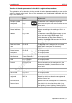
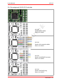
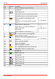
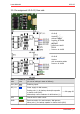
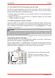
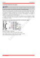
Table Of Contents
- 1. Getting started
- 2. Operation overview
- 3. Connections
- 3.1. Safety instructions
- 3.2. Safe and correct soldering
- 3.3. Avoiding irreparable damage to the decoder!
- 3.4. Pin assignment LD-G-43 | Front side
- 3.5. Pin assignment LD-G-43 | Rear side
- 3.6. Using decoders with interface connectors
- 3.7. Use of the LD-G-43 in locomotives with AC motor
- 3.8. Mounting decoders without interface
- 3.9. Connecting LEDs to the function outputs
- 3.10. Connecting inductive loads
- 3.11. Connecting the switching inputs
- 3.12. Connecting a backup capacitor or buffer circuit
- 3.13. Connection of a SUSI module
- 3.14. Completion
- 4. Programming
- 5. Configuration variables and registers
- 5.1. Overview configuration variables LD-G-43
- 5.2. Basic settings
- 5.3. Setting the address
- 5.4. Setting the motor control
- 5.5. Function mapping
- 5.6. Effects of the outputs
- 5.7. Settings for the switching inputs
- 5.8. RailCom and DCC-A settings
- 5.9. Settings for driving operation
- 5.10. Settings for analogue mode
- 5.11. Sensivity of the overload protection
- 5.12. Auxiliary functions
- 5.13. Information
- 6. Checklist for troubleshooting and error correction
- 7. Technical data
- 8. Warranty, EU conformity & WEEE

tams elektronik
tams elektronik LD-G-43
3.5. Pin assignment LD-G-43 | Rear side
LD-G-43
Versions:
without cables
Item no. 41-04430
NEM 652
Item no.41-04432
PluX22
Item no. 41-04433
LD-G-43
Version:
with connection cables
Item no. 41-04431
Rear
side
Colour of
wire
Connection
(for use of settings in state of delivery)
IN1 / IN2 grey Switching inputs
RC / V+ blue Power supply for Hall sensors;
Positive pole (+) for backup electrolytic capacitor
or buffer circuit (UPS).
Alternatively: return conductor for all functions (+)
--> Info page 28
UPS green Control line for buffer circuit
GND brown Earth connection for reed contacts / Hall sensors;
Minus pole (-) for backup capacitor or buffer circuit (UPS)
Ma
Connections | 27