
Manual
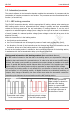
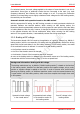
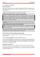
Table Of Contents
- 1. Getting started
- 2. Operation overview
- 3. Connections
- 3.1. Safety instructions
- 3.2. Safe and correct soldering
- 3.3. Avoiding irreparable damage to the decoder!
- 3.4. Pin assignment LD-G-43 | Front side
- 3.5. Pin assignment LD-G-43 | Rear side
- 3.6. Using decoders with interface connectors
- 3.7. Use of the LD-G-43 in locomotives with AC motor
- 3.8. Mounting decoders without interface
- 3.9. Connecting LEDs to the function outputs
- 3.10. Connecting inductive loads
- 3.11. Connecting the switching inputs
- 3.12. Connecting a backup capacitor or buffer circuit
- 3.13. Connection of a SUSI module
- 3.14. Completion
- 4. Programming
- 5. Configuration variables and registers
- 5.1. Overview configuration variables LD-G-43
- 5.2. Basic settings
- 5.3. Setting the address
- 5.4. Setting the motor control
- 5.5. Function mapping
- 5.6. Effects of the outputs
- 5.7. Settings for the switching inputs
- 5.8. RailCom and DCC-A settings
- 5.9. Settings for driving operation
- 5.10. Settings for analogue mode
- 5.11. Sensivity of the overload protection
- 5.12. Auxiliary functions
- 5.13. Information
- 6. Checklist for troubleshooting and error correction
- 7. Technical data
- 8. Warranty, EU conformity & WEEE

tams elektronik
tams elektronik LD-G-43
Output for buffer circuit
A special output is provided for the connection of a buffer circuit according to RCN-530 (e.g.
UPS-mini). Alternatively, it can be used to connect another consumer with a maximum current
of 100 mA.
By default, the output is switched on after a short waiting time after switching on the decoder
in order to load the buffer. The length of the waiting time varies randomly. This avoids that
several buffer circuits on the layout start the charging process at the same time immediately
after switching on and thus cause the collapse of the power supply.
With the function mapping, one or more functions can be assigned to this output, with which
the automatic charging of the buffer is activated and deactivated during operation. On
delivery, no function is assigned to the special function "UPS".
SUSI interface
The locomotive decoder LD-G-43 has a SUSI interface according to RailCommunity standard
RCN-600 in the version "classic SUSI", to which an external SUSI module (e.g. a sound
module) can be connected. The SUSI module is read out, programmed and controlled via the
decoder.
The locomotive decoder transmits the status of the functions and the speed level set at the
control unit to the SUSI module. This influences speed-dependent functions of the SUSI
module (e.g. the motor noise).
2.7. Triggering the actions
The switching on and off of the function outputs as well as the (de)activation of the special
functions is carried out
by the assigned function(s) and / or
automatically via the switching input. The switching input is triggered via external contacts,
e.g. via reed contacts or Hall sensors in combination with permanent magnets in the track.
Assignment of actions to functions (function mapping)
The assignment of the actions controlled by the decoder to the functions is freely selectable,
separately for forward and reverse motion.
Actions
DCC format MM format
Outputs F0f, F0r, AUX1 … AUX6 on/off
F0 to F28
F0 to F4
F5 to F8 with
2. Adresse
Uninterruptible power supply (UPS) on/off
Stop/start (STOP) with a function active/inactive
Shunting gear (SG) active/inactive
Acceleration and brake delay (ABD) active/inactive
Operation overview | 19